
HP 640 ProBook G3 Notebook PC & HP 650 ProBook G3 Notebook PC - Maintenance and Service Guide
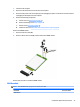
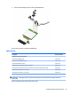
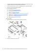
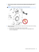
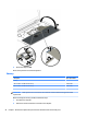
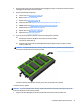
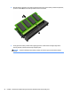
Table Of Contents
- Product description
- External component identification
- Illustrated parts catalog
- Removal and replacement procedures preliminary requirements
- Removal and replacement procedures for Authorized Service Provider parts
- Component replacement procedures
- Service door
- Battery
- Hard drive
- Solid-state drive (select products only)
- WWAN module (select products only)
- WLAN module
- Optical drive
- Keyboard
- Memory
- Hinge cover
- Base enclosure
- System board
- Fan and heat sink assembly
- Optical drive board
- Top cover and TouchPad
- RTC battery
- Speaker
- Power button board
- Fingerprint reader (select products only)
- Smart card reader
- Near Field Communication module
- Audio board
- Serial board
- Display assembly
- Component replacement procedures
- Computer Setup (BIOS), TPM, and HP Sure Start
- Using HP PC Hardware Diagnostics (UEFI)
- Backing up, restoring, and recovering
- Specifications
- Power cord set requirements
- Statement of memory volatility
- Recycling
- Index
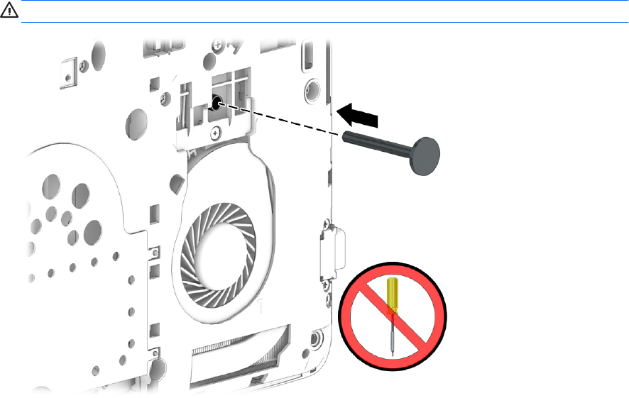
3. Gently insert a Torx screwdriver or other blunt tool into the keyboard release opening under the memory
module, and then press gently on the back of the keyboard until the keyboard disengages from the
computer.
CAUTION: Press gently to avoid damaging the mylar on the back of the keyboard.
4. Rotate the keyboard downward (1) onto the top cover (1), and then release and disconnect the following
connectors and cables:
●
Release the keyboard connector (2) and then remove the cable (3).
●
For products with a backlit keyboard, release the backlight connectors (4) and (6), and then
remove the cables (5) and (7).
Component replacement procedures 49