
HP 640 ProBook G3 Notebook PC & HP 650 ProBook G3 Notebook PC - Maintenance and Service Guide
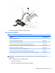

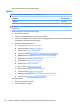
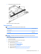
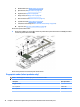
Table Of Contents
- Product description
- External component identification
- Illustrated parts catalog
- Removal and replacement procedures preliminary requirements
- Removal and replacement procedures for Authorized Service Provider parts
- Component replacement procedures
- Service door
- Battery
- Hard drive
- Solid-state drive (select products only)
- WWAN module (select products only)
- WLAN module
- Optical drive
- Keyboard
- Memory
- Hinge cover
- Base enclosure
- System board
- Fan and heat sink assembly
- Optical drive board
- Top cover and TouchPad
- RTC battery
- Speaker
- Power button board
- Fingerprint reader (select products only)
- Smart card reader
- Near Field Communication module
- Audio board
- Serial board
- Display assembly
- Component replacement procedures
- Computer Setup (BIOS), TPM, and HP Sure Start
- Using HP PC Hardware Diagnostics (UEFI)
- Backing up, restoring, and recovering
- Specifications
- Power cord set requirements
- Statement of memory volatility
- Recycling
- Index
3. Lift the speaker assembly to remove it.(3).
Reverse this procedure to install the speaker.
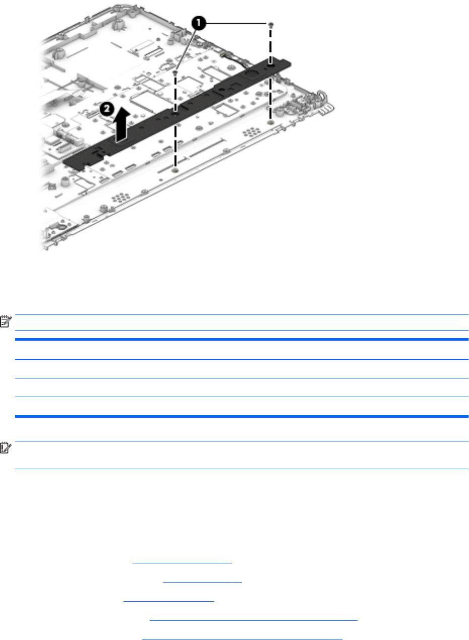
Power button board
NOTE: The power button board spare part kit includes the cable.
Description Spare part number
Power button board
For 14" products 840693-001
For 15" products 840744-001
IMPORTANT: Make special note of each screw and screw lock size and location during removal and
replacement.
Before removing the power button board, follow these steps:
1. Shut down the computer.
2. Disconnect all external devices connected to the computer.
3. Remove the following components:
a. Service door (see Service door on page 37).
b. Remove the battery (see Battery on page 38)
c. Hard drive (see Hard drive on page 39).
d. Solid-state drive (see Solid-state drive (select products only) on page 41).
e. WWAN module (see WWAN module (select products only) on page 42).
Component replacement procedures 69