
Manual
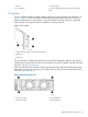

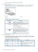
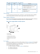
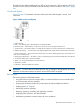
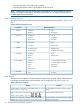
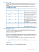


Table 11 EMU display groups
DescriptionDisplay groupDisplay
The enclosure number is the default display and is a decimal number
in the range 00 through 14. See “Enclosure number feature” (page
32) for detailed information.
Enclosure NumberEn
This display group has a single sublevel display that defines the
enclosure bay 1 loop ID. Valid loop IDs are in the range 00 through
7F.
Bay 1 Loop IDLi
This display group has two two-digit displays that define the reporting
group number in the range 0000 through 4095.
Reporting GrouprG
This display group provides control over the audible alarm or horn.
The sublevel displays are audible alarm enabled (on) or audible alarm
Audible AlarmAu
disabled (oF). See “Audible alarm operations ” (page 30) for detailed
information.
This display group defines the EMU code firmware version.Firmware RevisionFr
This display group reads Er when there is an error condition.Error ConditionEr
NOTE: Any time you press and release the bottom pushbutton, the display will change to En, Li,
rG, Au, or Er.
A flashing alphanumeric display indicates that you can edit an address or state, or view a condition
report.
EMU pushbutton status indicators
The pushbutton status indicators display error conditions and the state of the audible alarm.
• When an error condition exists, the top pushbutton status indicator is On.
For a single error condition, the status indicator is On until the error condition is viewed.◦
◦ For multiple errors, the status indicator is On until the last error condition is viewed.
• The bottom pushbutton indicator is On only when the alarm is muted or disabled.
Audible alarm operations
Whenever an error condition exists, the audible alarm automatically sounds until all errors are
corrected. You have the option of either muting or disabling the alarm.
• Disabling the audible alarm prevents it from sounding for any error condition.
• Muting the alarm silences it for the existing condition, but any new condition causes the alarm
to sound.
Audible alarm patterns
The audible alarm sound pattern differs depending on the type of error condition. See
Table 12 (page 30) for the duration and the approximate relationship of these alarms. The most
severe, active error condition controls the alarm pattern.
Table 12 Audible alarm sound patterns
Cycle 2Cycle 1Condition type
UNRECOVERABLE
CRITICAL
30 Enterprise Virtual Array hardware components