Hardware Reference Guide HP 402 G1 Small Form Factor Business PC
© Copyright 2014 Hewlett-Packard Development Company, L.P. The information contained herein is subject to change without notice. Microsoft® and Windows® are U.S. registered trademarks of Microsoft Corporation. The only warranties for HP products and services are set forth in the express warranty statements accompanying such products and services. Nothing herein should be construed as constituting an additional warranty. HP shall not be liable for technical or editorial errors or omissions contained herein.
About This Book This guide provides basic information for upgrading the HP Business PC. WARNING! Text set off in this manner indicates that failure to follow directions could result in bodily harm or loss of life. CAUTION: Text set off in this manner indicates that failure to follow directions could result in damage to equipment or loss of information. NOTE: Text set off in this manner provides important supplemental information.
iv About This Book
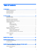
Table of contents 1 Product features ................................................................................................................................................ 1 Standard configuration features ........................................................................................................... 1 Front panel components ....................................................................................................................... 1 Rear panel components ...................
Cleaning ............................................................................................................................. 27 Safety ................................................................................................................................. 27 Shipping preparation .......................................................................................................................... 27 Index .................................................................................
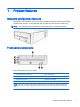
1 Product features Standard configuration features Features may vary depending on the model. For a complete listing of the hardware and software installed in the computer, run the diagnostic utility (included on some computer models only). NOTE: This computer model can be used in a tower orientation or a desktop orientation. Front panel components Drive configuration may vary by model. 1 Slim optical disc drive (optional) 5 USB 2.0 Port (black) 2 USB 2.
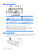
Rear panel components 1 Power Cord Connector 8 DVI-D Monitor Connector (white) 2 Serial Connector (green) 9 VGA Monitor Connector (blue) 3 RJ-45 Network Connector 10 USB 2.0 Ports (black) 4 PCI x16 Expansion Card Slot Cover 11 USB 3.
2 Hardware upgrades Serviceability features The computer includes features that make it easy to upgrade and service. No tools are needed for most of the installation procedures described in this chapter. Warnings and cautions Before performing upgrades be sure to carefully read all of the applicable instructions, cautions, and warnings in this guide.
Removing the computer access panel To access internal components, you must remove the access panel: 1. Remove/disengage any security devices that prohibit opening the computer. 2. Remove all removable media, such as optical discs or USB flash drives, from the computer. 3. Turn off the computer properly through the operating system, then turn off any external devices. 4. Disconnect the power cord from the power outlet and disconnect any external devices.
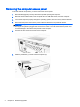
Replacing the computer access panel 1. Place the panel on the computer (1), and then slide it forward (2). 2. Fasten the two screws (3) to secure the panel in place. Changing from desktop to tower configuration The computer can be used in either a horizontal or a tower orientation. 1. Remove/disengage any security devices that prohibit opening the computer. 2. Remove all removable media, such as optical discs or USB flash drives, from the computer. 3.
6. Reconnect the power cord and any external devices, then turn on the computer. NOTE: Ensure at least 10.2 centimeters (4 inches) of space on all sides of the computer remains clear and free of obstructions. 7. Lock any security devices that were disengaged when the access panel was removed. Installing additional memory The computer comes with double data rate 3 synchronous dynamic random access memory (DDR3SDRAM) dual inline memory modules (DIMMs).
● The system will operate in single channel mode if the DIMM sockets are populated in one channel only. ● The system will operate in a higher-performing dual channel mode if the memory capacity of the DIMM in Channel A is equal to the memory capacity of the DIMM in Channel B. ● The system will operate in flex mode if the memory capacity of the DIMM in Channel A is not equal to the memory capacity of the DIMM in Channel B.
6. Locate the DIMM sockets. 7. Open both latches of the memory module socket (1), and insert the memory module into the socket (2). NOTE: A memory module can be installed in only one way. Match the notch on the module with the tab on the memory socket. For maximum performance, populate the sockets so that the memory capacity is spread as equally as possible between Channel A and Channel B. Refer to Populating DIMM sockets on page 6 for more information. 8.
The computer should automatically recognize the additional memory the next time you turn on the computer. Removing or installing an expansion card The computer has one PCI Express x1 expansion slot, one PCI Express x16 expansion slot, and two PCI expansion slots. NOTE: The PCI Express slots support only low profile cards. You can install a PCI Express x1, x4, x8, or x16 expansion card in the PCI Express x16 slot.
9. a. If you are installing an expansion card in a vacant PCI x1 socket or a PCI socket, push out the appropriate expansion slot cover on the back of the chassis. b. If you are installing an expansion card in a vacant PCI x16 socket, remove the appropriate expansion slot cover on the back of the chassis. Pull the slot cover straight up then away from the inside of the chassis. c.
Installing and removing drives When installing drives, follow these guidelines: ● The Serial ATA (SATA) hard drive must be connected to the SATA connector on the system board labeled SATA1. ● Connect an optical disc drive to the SATA connector on the system board labeled SATA2. ● The power cable for the drives is a dual-headed cable coming from the power supply. The first connector is routed to the hard drive and the second connector is routed to the slim optical disc drive.
6. Disconnect the power cable and data cable from the rear of the optical disc drive. CAUTION: When removing the cables, pull the tab or connector instead of the cable itself to avoid damaging the cable. 7. Unfasten the screw securing the optical disc drive cage to the chassis. Retain the screw. 12 8. Press the both sides optical disk drive latch to release the optical disc drive cage and slide the cage away from the edge of the chassis. 9. Lift the optical disc drive cage out of the chassis.
10. Open the latch on the side of the optical disc drive cage. 11. Push the optical disc drive out through the front of the cage.
Installing a slim optical disc drive 1. Remove/disengage any security devices that prohibit opening the computer. 2. Remove all removable media, such as optical discs or USB flash drives, from the computer. 3. Turn off the computer properly through the operating system, then turn off any external devices. 4. Disconnect the power cord from the power outlet and disconnect any external devices.
8. Align the optical disc drive above the hard drive with the disc tray opening toward the front of the chassis. Lower the optical disc drive onto the hard drive and next to the power supply. 9. Align the latch on the front edge of the optical disc drive cage with the slots on the front edge of the chassis. Hold both sides of the latch down and slide the drive cage forward until the latch engages. 10. Fasten the screw to secure the optical disc drive cage to the chassis. 11.
12. Connect the opposite end of the data cable to the SATA2 connector on the system board. 13. Replace the computer access panel. 14. Reconnect the power cord and any external devices, then turn on the computer. 15. Lock any security devices that were disengaged when the access panel was removed. Removing and replacing a 3.5-inch hard drive NOTE: Before you remove the old hard drive, be sure to back up the data from the old hard drive so that you can transfer the data to the new hard drive. 1.
7. Disconnect the power cable and data cable from the back of the hard drive. 8. Press the tab to disengage the latch securing the hard drive in place. 9. Slide the hard drive away from the edge of the chassis to disengage the hard drive cage, and then lift it out of the chassis. 10. Open the latch on the side of the hard drive cage.
11. Remove the two screws from the side of the hard drive cage, and then slide the hard drive out of the cage. Retain the screws to use on the new hard drive. 12. Slide the new hard drive all the way into the hard drive cage. Be sure the hard drive is positioned properly. The latch tab that secured the hard drive cage to the chassis is on the bottom side of the drive cage.
15. Hold the hard drive cage with the connectors next to the power supply and align the openings in the cage bottom with the raised clips on the bottom of the chassis. 16. Set the cage down and slide it left to engage the clips on the chassis beneath the cage. Be sure the cage latch slides over and engages the chassis tab to lock the hard drive cage in place. 17. Connect the power cable and data cable to the back of the hard drive.
18. Connect the opposite end of the data cable to the SATA1 connector on the system board. 19. Replace the slim optical disc drive. For instructions, go to Installing a slim optical disc drive on page 14. 20. Replace the access panel. 21. Reconnect the power cord and turn on the computer. 22. Lock any security devices that were disengaged when the access panel was removed.
Installing a security lock The security locks in the following sections can be used to secure the computer. Cable lock The cable lock can be used to secure the computer. Padlock A padlock can be used to secure the access panel to the computer.
A Battery replacement The battery that comes with the computer provides power to the real-time clock. When replacing the battery, use a battery equivalent to the battery originally installed in the computer. The computer comes with a 3-volt lithium coin cell battery. WARNING! The computer contains an internal lithium manganese dioxide battery. There is a risk of fire and burns if the battery is not handled properly. To reduce the risk of personal injury: Do not attempt to recharge the battery.
b. Slide the replacement battery into position, positive side up. The battery holder automatically secures the battery in the proper position. Type 2 a. To release the battery from its holder, squeeze the metal clamp that extends above one edge of the battery. When the battery pops up, lift it out (1). b. To insert the new battery, slide one edge of the replacement battery under the holder’s lip with the positive side up.
b. Insert the new battery and position the clip back into place. NOTE: After the battery has been replaced, use the following steps to complete this procedure. 8. Replace the computer access panel. 9. Plug in the computer and turn on power to the computer. 10. Reset the date and time, your passwords, and any special system setups using Computer Setup. 11. Lock any security devices that were disengaged when the computer access panel was removed.
B Electrostatic discharge A discharge of static electricity from a finger or other conductor may damage system boards or other static-sensitive devices. This type of damage may reduce the life expectancy of the device. Preventing electrostatic damage To prevent electrostatic damage, observe the following precautions: ● Avoid hand contact by transporting and storing products in static-safe containers. ● Keep electrostatic-sensitive parts in their containers until they arrive at static-free workstations.
C Computer operating guidelines, routine care and shipping preparation Computer operating guidelines and routine care Follow these guidelines to properly set up and care for the computer and monitor: 26 ● Keep the computer away from excessive moisture, direct sunlight, and extremes of heat and cold. ● Operate the computer on a sturdy, level surface. Leave a 10.2-cm (4-inch) clearance on all vented sides of the computer and above the monitor to permit the required airflow.
Optical disc drive precautions Be sure to observe the following guidelines while operating or cleaning the optical disc drive. Operation ● Do not move the drive during operation. This may cause it to malfunction during reading. ● Avoid exposing the drive to sudden changes in temperature, as condensation may form inside the unit. If the temperature suddenly changes while the drive is on, wait at least one hour before you turn off the power.
Index A access panel removal 4 replacement 5 L locks cable lock 21 B battery replacement 22 C computer operating guidelines 26 D DIMMs. See memory drives cable connections 11 installation 11 E electrostatic discharge, preventing damage 25 expansion card installation 9 removal 9 F front panel components 1 H hard drive (3.5-inch) installation 16 removal 16 I installation guidelines 3 installing 3.