
Maintenance and Service Guide
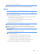
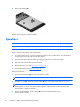
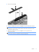
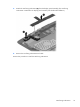
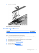
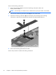
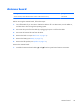
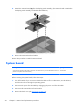
Table Of Contents

4. Remove the left speaker (5).
5. Unsolder the red (1) and black speaker cables (2) from the system board speaker connectors.
NOTE: When installing the left speaker, the red speaker cable should be soldered to the system
board speaker “positive” terminal. The black speaker cable should be soldered to the system
board speaker “negative” terminal.
6. Remove the two Phillips PM1.25×4.0 screws (3) that secure the right speaker to the
display panel assembly.
NOTE: The screws that secure the right speaker to the display panel assembly include washers.
Make sure these washers are installed when installing the right speaker.
Speakers
17