
DDR4 Memory Technology
2
Technical white paper | DDR4 Memory Technology on HP Z Workstations
DDR4 Interface
The DDR4 memory interface connects the Dual In-line Memory Module (DIMM) to the CPU and consists of address/
command and data bus groups. The data bus group is comprised of 64 bits on non-ECC systems and 72 bits on
processors and systems that support ECC memory.
Memory Module makeup
A DDR4 DIMM consists of a number of distinct parts or components such as: Printed Circuit Board (PCB), DRAM chips,
buer register in the case of RDIMMs and LR DIMMs, and various discrete components. The DRAM chips used dene
the principal characteristics of a DIMM.
DRAM characteristics
Dynamic Random Access Memory (DRAM) chips come in dierent capacities. Today, 4 Gigabit (Gb) DRAMs are the
most common and considered to be the best value. 8 Gb DRAMs are available, but carry a price premium.
DRAM chips can support 4, 8, or 16 data bits of width per chip. The width of the DRAM is designated by x#. For
example, a 4 bit width DRAM is x4. The size and the width of a DRAM provide exibility in creating DIMMs of dierent
organisations to create the optimal DIMM at each capacity for each type. Since some DRAMs are single, dual or quad
dies, the number of chips on a DIMM is an unreliable way to guess the type of DRAM used.
Three dimensional stacking or 3DS, is a new IC packaging technology that uses die stacking technology. 3DS allows
for stacking of multiple DRAMs to support larger capacities at a lower cost and better performance.
ECC protection
Error Correction Code (ECC) provides protection against some data bit corruption events, either in the DRAM chips on
the DIMM, or on the memory bus and in the platform’s memory controller. On ECC DIMMs, 8 additional data bits are
implemented, giving a data bus width of 72 bits instead of 64 bits as on non-ECC DIMMs.
Additional DRAM chips provide the additional memory space needed for the ECC protection. For each data transfer
to the DIMM during a write event, an ECC code is calculated by the memory controller and stored along with the data
to be written. On subsequent reads, the memory controller checks the ECC code and can determine if single-bit or
multiple-bit errors occurred. It will correct single-bit errors automatically, thereby avoiding propagation of corrupted
data to the system. Multi-bit errors cannot be corrected on platforms with independent memory channels, as in the
case on most current workstation systems. However, multi-bit errors can be detected and, on HP Workstations, will
immediately trigger a Machine Check event which will halt the operating system, thus preventing the propagation of
corrupted data.
Non-ECC DIMMs have no extra data bits and so do not provide this added protection against incorrect data bit values.
Non-ECC memory does not detect or correct single-bit or multi-bit errors. This can lead to system crashes, or data
corruption without alerting the user. Data corruption can take many forms, such as: applications processing incorrect
data, delivering incorrect results, application crashes, or le corruption. File corruption can lead to an inability to
reopen a le, or the need to reinstall either an application or the operating system. ECC improves protection against
corruption of data in memory and should be used in mission-critical applications or high-reliability, 24x7x365
environments.
Ranks
A Rank is dened to be a group of DRAM chips with matching characteristics such that the sum of the DRAM widths is
either 64 bits (non-ECC) or 72 bits (ECC). Two examples are:
• 1 Rank = 8 x [x8 DRAM] = 64 bits
• 1 Rank = 18 x [x4 DRAM] = 72 bits
To increase capacity on a DIMM, additional ranks can be added. A memory rank is a set of DRAMs connected by a chip
select line. This allows multiple DRAMS to be selected at the same time, so that each can provide their share (4, 8, or
16 data bits) of the 64 or 72 bit bus width.
DDR4 Memory Module types
There are three types of DIMMs supported in HP Workstations, depending upon specic platform model support:
unbuered, registered, and load reduced. Note that these DIMM types cannot be intermixed in a system.
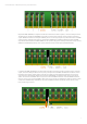
Unbuered DIMMs (UDIMMs) are high volume DIMMs used in most consumer and entry enterprise applications. As the
name implies, none of the signals are buered. The data and command/address signals go directly into the DRAMs,
as shown in the gure below. All UDIMMs support parity protection on the command and address signals. There are
two types of UDIMMs: non-ECC and ECC. Non-ECC UDIMMs can support x8 and x16 DRAMs. ECC UDIMMs can only
support x8 DRAMs.
There are two dierent types of UDIMM form factors: Standard DIMMs and Small Outlined (SO) DIMMs. Standard
DIMMs are found in most desktop workstations where space is not a concern. SO DIMMs are a smaller version of a
DIMM. They are usually used in laptops and desktops workstations that are tight with space.