
Owner's manual


Page 22-35
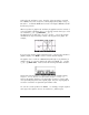
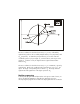
The stress condition for which the shear stress, τ’
xy
, is zero, indicated by
segment D’E’, produces the so-called principal stresses, σ
P
xx
(at point D’) and
σ
P
yy
(at point E’). To obtain the principal stresses you need to rotate the
coordinate system x’-y’ by an angle
φ
n
, counterclockwise, with respect to the
system x-y. In Mohr’s circle, the angle between segments AC and D’C
measures 2
φ
n
.
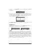
The stress condition for which the shear stress, τ’
xy
, is a maximum, is given by
segment F’G’. Under such conditions both normal stresses, σ’
xx
= σ’
yy
, are
equal. The angle corresponding to this rotation is
φ
s
. The angle between
segment AC and segment F’C in the figure represents 2
φ
s
.
Modular programming
To develop the program that will plot Mohr’s circle given a state of stress, we
will use modular programming. Basically, this approach consists in
decomposing the program into a number of sub-programs that are created as