HP 5920&5900 Switch Series Installation Guide 5998-2852 Part number: 5998-2852a Document version: 6W104-20150115
Legal and notice information © Copyright 2015 Hewlett-Packard Development Company, L.P. No part of this documentation may be reproduced or transmitted in any form or by any means without prior written consent of Hewlett-Packard Development Company, L.P. The information contained herein is subject to change without notice.
Contents Preparing for installation ············································································································································· 1 Safety recommendations ·················································································································································· 3 Examining the installation site ································································································································
Maintenance and troubleshooting ···························································································································· 36 Power supply failure ······················································································································································ 36 Fan tray failure ·······························································································································································
Preparing for installation Table 1 describes HP 5920 and 5900 Switch Series models, power supplies, and fan trays.
• • • For regulatory identification purposes, the HP 5920AF-24XG and HP 5920AF-24XG TAA products are assigned Regulatory Model Numbers (RMNs). The Regulatory Model Numbers for these products are listed below. These regulatory numbers should not be confused with the marketing name HP 5920AF, or product codes JG296A and JG555A.
Product code RMN HP description JH038A BJNGA-AD0017 HP 5900AF-48G-4XG-2QSFP+ TAA-compliant Switch Safety recommendations To avoid any equipment damage or bodily injury, read the following safety recommendations before installation. Note that the recommendations do not cover every possible hazardous condition. • Before cleaning the switch, remove all power cords from the switch. Do not clean the switch with wet cloth or liquid. • Do not place the switch near water or in a damp environment.
• Lasting low relative humidity can cause washer contraction and ESD and bring problems including loose captive screws and circuit failure. • High temperature can accelerate the aging of insulation materials and significantly lower the reliability and lifespan of the switch. For the temperature and humidity requirements of different switch models, see "Appendix A Chassis views and technical specifications.
• Use electromagnetic shielding, for example, shielded interface cables, when necessary. Laser safety WARNING! Do not stare into any fiber port when the switch has power. The laser light emitted from the optical fiber might hurt your eyes. The switch is a Class 1 laser device. Installation tools The installation tools are not provided with the switch. Prepare them yourself.
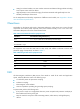
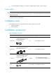
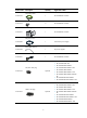
Product code Description Quantity Applicable models 1 All 5920&5900 switches 2 All 5920&5900 switches 1 All 5920&5900 switches 1 650 W DC power supply 1 All power supplies 1 All 5920&5900 switches Grounding cable 5184-6723 Grounding screw 5185-9579 Power supply filler module 5185-8676 DC power cord 5185-8688 Removable cable tie 5185-8748 Console cable 5185-8627 SFP/SFP+ dust plug 5185-8722 Optional • • • • • • • HP 5920AF-24XG HP 5920AF-24XG TAA HP 5900AF-48XG-4QSFP+ HP 5900AF-48XG-4Q
Installing the switch CAUTION: Keep the tamper-proof seal on a mounting screw on the chassis cover intact, and if you want to open the chassis, contact HP for permission. Otherwise, HP shall not be liable for any consequence caused thereby.
Switch model Installation method Requirements for the rack • Depth—A minimum of 1000 mm • HP 5920AF-24XG • HP 5920AF-24XG TAA • • • • • Using mounting brackets and short slide rails (provided) (39.37 in). • Distance between the front and rear rack posts—401 mm (15.79 in) to 895 mm (35.24 in).
Figure 3 Rack mounting rail kit (1) Chassis rail (2) Slide rail Rack-mounting procedures at a glance Figure 4 Rack-mounting procedure IMPORTANT: To make sure the switch is securely installed in the rack, you must install both the mounting brackets and rack mounting rail kit. NOTE: If a rack shelf is available, you can put the switch on the rack shelf, slide the switch to an appropriate location, and attach the switch to the rack with the mounting brackets.
Switch model • • • • • Grounding point Remarks HP 5900AF-48XG-4QSFP+. HP 5900AF-48XG-4QSFP+ TAA. • HP recommends that you use the HP 5900CP-48XG-4QSFP+. HP 5900CP-48XG-4QSFP+ TAA. HP 5900CP-48XG-4QSFP+8Gb FC B-F. • HP 5900AF-48XGT-4QSFP+. • HP 5900AF-48XGT-4QSFP+ One primary grounding point (with a grounding sign) and two auxiliary grounding points primary grounding point or auxiliary grounding point 1.
(1) Auxiliary grounding point 2 (2) Rear mounting position (3) Primary grounding point (4) Auxiliary grounding point 1 (5) Front mounting position Figure 7 Mounting and grounding positions of the HP 5900AF-48G-4XG-2QSFP+/HP 5900AF-48G-4XG-2QSFP+ TAA switch 2 3 1 (1) Auxiliary grounding point 2 (2) Rear mounting position (3) Primary grounding point (4) Auxiliary grounding point 1 4 5 (5) Front mounting position Attaching the mounting brackets and chassis rails to the chassis 1.
NOTE: • HP recommends that you use the primary grounding point or auxiliary grounding point 1 because the grounding cable and grounding screw that come with the switch are suitable only for these two grounding points. • To use auxiliary grounding point 2, you must prepare a grounding cable yourself. To connect the grounding cable: 1. Choose a grounding point. 2. Unpack the grounding cable and grounding screws. 3.
Figure 9 Attaching the front mounting brackets/chassis rails to the chassis Attaching the slide rails to the rack 1. Identify the rack attachment position for the slide rails. 2. Install cage nuts (user-supplied) in the mounting holes in the rack posts. 3. Align the screw holes in one slide rail with the cage nuts in the rack post on one side, and use screws (user supplied) to attach the slide rail to the rack, as shown in Figure 10. 4.
2. Verify that the mounting brackets and chassis rails have been securely attached to the switch chassis. 3. Verify that the slide rails have been correctly attached to the rear rack posts. 4. Install cage nuts (user-supplied) to the front rack posts and make sure they are at the same level as the slide rails. 5. Supporting the bottom of the switch, align the chassis rails with the slide rails on the rack posts, as shown in Figure 11.
Figure 12 Mounting the switch in the rack (2) Grounding the switch WARNING! Correctly connecting the switch grounding cable is crucial to lightning protection and EMI protection. The power input end of the switch has a noise filter, whose central ground is directly connected to the chassis to form the chassis ground (commonly known as PGND).
To connect the grounding cable: 1. Attach the two-hole grounding lug at one end of the grounding cable to a grounding point on the switch chassis. See "Connecting the grounding cable." 2. Remove the hex nut of a grounding post on the grounding strip. 3. Attach the ring terminal at the other end of the grounding cable to a grounding post on the grounding strip, and fasten the ring terminal with the removed hex nut.
Figure 14 Grounding through the PE wire of the AC power cord 2 1 (1) Three-wire AC power cable (2) Chassis rear panel NOTE: To guarantee the grounding effect, use the grounding cable provided with the switch to connect to the grounding strip in the equipment room as long as possible. Installing/removing a fan tray CAUTION: To ensure good ventilation for the switch: • Install two fan trays of the same model on the switch. • Do not power on the switch when no or only one fan tray is installed.
Select fan trays as required. For the available fan trays and their specifications, see "Fan trays." To install a fan tray: 1. Wear an ESD wrist strap and make sure it makes good skin contact and is reliably grounded. 2. Unpack the fan tray and verify that the fan tray model is correct. 3.
1. Wear an ESD wrist strap and make sure it makes good skin contact and is reliably grounded. 2. Loosen the captive screw of the fan tray with a Phillips screwdriver until it is fully disengaged from the switch chassis. 3. Grasp the handle of the fan tray with one hand and pull the fan tray part way out the slot. Support the fan tray bottom with the other hand, and pull the fan tray slowly along the guide rails out of the slot. 4. Put away the removed fan tray in an antistatic bag for future use.
Installing a power supply CAUTION: • Follow the forward inertia of the power supply when inserting it into the chassis, and make sure the power supply has firm contact with the connectors on the backplane. • To prevent damage to the connectors inside the switch chassis, insert the power supply gently. If you encounter a hard resistance while inserting the power supply, pull out the power supply and insert it again.
Figure 20 Installing a filler module Removing a power supply CAUTION: If the switch has two power supplies, removing one power supply does not affect the operation of the switch. If the switch has only one power supply, removing the power supply powers off the switch. To remove a 650W AC or 650W DC power supply from the switch: 1. Wear an ESD wrist strap and make sure it makes good skin contact and is reliably grounded. 2.
Figure 21 Removing the DC power cord (1) Press the tabs on the power cord connector with your thumb and forefinger (2) Pull the power cord connector out Figure 22 Removing the power supply (1) Pivot the latch to the right with your thumb (2) Pull the power supply out 22
Connecting the power cord CAUTION: • Provide a circuit breaker for each power supply. • Before you connect the power cord for a power supply, make sure the circuit breaker for the power supply is turned off. Connecting the 650W AC power supply 1. Insert the female connector of the AC power cord supplied with the power supply into the power receptacle on the power supply. 2. Use a cable tie to secure the power cord to the handle of the power supply, as shown in Figure 23. 3.
Figure 24 Connecting the 650W DC power supply Verifying the installation After you complete the installation, verify that: • There is enough space for heat dissipation around the switch, and the rack is stable. • The grounding cable is securely connected. • The correct power source is used. • The power cords are correctly connected. • All the interface cables are cabled indoors.
Accessing the switch for the first time Setting up the configuration environment The first time you access the switch you must use a console cable to connect a configuration terminal, for example, a PC, to the console port on the switch.
RJ-45 Signal DB-9 Signal 3 TXD 2 RXD 4 SG 5 SG 5 SG 5 SG 6 RXD 3 TXD 7 DSR 4 DTR 8 CTS 7 RTS To connect a terminal (for example, a PC) to the switch: 1. Plug the DB-9 female connector of the console cable to the serial port of the PC. 2. Connect the RJ-45 connector to the console port of the switch. NOTE: • Identify the mark on the console port and make sure you are connecting to the correct port. • The serial ports on PCs do not support hot swapping.
versions. For more information about Boot ROM menu options, see the release notes for the switch software. After the startup completes, you can access the CLI to configure the switch. For more information about the configuration commands and CLI, see HP 5920 & 5900 Switch Series Configuration Guide and HP 5920 & 5900 Switch Series Command References.
Setting up an IRF fabric You can use HP IRF technology to connect and virtualize the switches into a large virtual switch called an "IRF fabric" for flattened network topology, and high availability, scalability, and manageability. To set up IRF links between the switches, use SFP+ ports, 1/10-GE Ethernet ports, or QSFP+ ports.
Step Description Plan the installation site and IRF fabric setup parameters: 1. Plan IRF fabric setup. • • • • • Planning IRF fabric size and the installation site. Identifying the master switch and planning IRF member IDs. Planning IRF topology and connections. Identifying physical IRF ports on the member switches. Planning the cabling scheme. 2. Install IRF member switches. See "Installing the switch in a 19-inch rack." 3. Connect ground wires and power cords.
NOTE: IRF member switches will automatically elect a master. You can affect the election result by assigning a high member priority to the intended master switch. For more information about master election, see HP 5920 & 5900 Switch Series IRF Configuration Guide. Prepare an IRF member ID assignment scheme. An IRF fabric uses member IDs to uniquely identify and manage its members, and you must assign each IRF member switch a unique member ID.
Figure 29 IRF fabric in ring topology 1 2 3 IRF-port1 IRF-port2 1 IRF-port2 IRF-port1 IRF-port1 IRF-port2 2 3 Identifying physical IRF ports on the member switches Identify the SFP+ or QSFP+ ports to be used for IRF connections on the member switches according to your topology and connection scheme.
• On the HP 5900AF-48G-4XG-2QSFP+ and 5900AF-48G-4XG-2QSFP+ TAA switches, SFP+ ports numbered 49, 50, 51, and 52 form one group. • On the HP 5900AF-48XGT-4QSFP+ and HP 5900AF-48XGT-4QSFP+ TAA switches, the 1/10-GE ports are grouped by port number in ascending order, starting from one. Every four 1/10-GE ports form one group.
Figure 30 Connecting the switches in one rack 1 2 3 4 Figure 31 IRF fabric topology Connecting the IRF member switches in a ToR solution You can install IRF member switches in different racks side by side to deploy a top of rack (ToR) solution. Figure 32 shows an example for connecting four top of rack IRF member switches by using SFP+/QSFP+ DAC cables, and SFP+/QSFP+ transceiver modules, and optical fibers. The topology is the same as Figure 31.
After you install the IRF member switches, power on the switches, and log in to each IRF member switch to configure their member IDs, member priorities, and IRF port bindings. For more information, see HP 5920 & 5900 Switch Series Fundamentals Configuration Guide. Follow these guidelines when you configure the switches: • Assign the master switch higher member priority than any other switch. • Bind physical ports to IRF port 1 on one switch and to IRF port 2 on the other switch.
NOTE: To avoid IP address collision and network problems, configure a minimum of one multi-active detection (MAD) mechanism to detect the presence of multiple identical IRF fabrics and handle collisions. For more information about MAD detection, see HP 5920 & 5900 Switch Series IRF Configuration Guide.
Maintenance and troubleshooting Power supply failure You can use the LEDs on the power supply to identify a power supply failure. For more information about the LEDs on a power supply, see HP A58x0AF 650W AC (JC680A) & 650W DC (JC681A) Power Supplies User Guide. If the LEDs on the power supply are not steady green (active) or blinking green (standby), the power supply is faulty. To resolve the problem: 1. Verify that the power cord is connected securely. 2.
1. Verify that the power system is operating correctly. 2. Verify that the switch is operating correctly. 3. Verify that the console cable has been connected correctly. 4. Verify that the following settings are configured for the terminal: { Baud rate—9600. { Data bits—8. { Parity—None. { Stop bits—1. { Flow control—None. 5. Verify that the console cable is not faulty. 6. If the problem persists, contact HP support.
Appendix A Chassis views and technical specifications Chassis views HP 5920AF-24XG/HP 5920AF-24XG TAA Figure 33 Front panel (1) SFP+ port (2) SFP+ port LED (3) Management Ethernet port (4) Console port (5) System status LED (SYS) (6) ACT LED for the management Ethernet port (7) LINK LED for the management Ethernet port Figure 34 Rear panel (1) Power supply slot 1 (2) Power supply slot 2 (3) Fan tray slot 1 (4) Fan tray slot 2 The HP 5920AF-24XG and 5920AF-24XG TAA switches come with the power s
Figure 35 Left side panel (1) Primary grounding point (2) Auxiliary grounding point 1 HP 5900AF-48XG-4QSFP+/HP 5900AF-48XG-4QSFP+ TAA/HP 5900CP-48XG-4QSFP+/HP 5900CP-48XG-4QSFP+ TAA/HP 5900CP-48XG-4QSFP+8Gb FC B-F Figure 36 Front panel (1) SFP+ port (2) SFP+ port LED (3) QSFP+ port (4) QSFP+ port LED (5) System status LED (SYS) Figure 37 Rear panel (1) Grounding screw (auxiliary grounding point 2) (2) Management Ethernet port (3) Console port (4) Fan tray slot 1 (5) Fan tray slot 2 (6) Power
supplies for the switch as needed. In this figure, two 650W AC power supplies are installed. For more information about installing and removing the power supply, see "Installing/removing a power supply." The HP 5900AF-48XG-4QSFP+, 5900AF-48XG-4QSFP+ TAA, 5900CP-48XG-4QSFP+, 5900CP-48XG-4QSFP+ TAA, and 5900CP-48XG-4QSFP+8Gb FC B-F switches also come with the fan tray slots empty.
(5) Fan tray slot 2 (6) Power module slot 1 (7) Power module slot 2 (8) LINK LED for the management Ethernet port (9) ACT LED for the management Ethernet port (10) USB port The HP 5900AF-48XGT-4QSFP+ and HP 5900AF-48XGT-4QSFP+ TAA switches come with the power supply slots empty and the filler modules for the slots as accessories. You can install one or two power supplies for the switch as needed. In Figure 43, two 650W AC power supplies are installed.
Figure 43 Rear panel (1) Grounding screw (auxiliary grounding point 2) (2) Management Ethernet port (3) Console port (4) Fan tray slot 1 (5) Fan tray slot 2 (6) Power supply slot 1 (7) Power supply slot 2 (8) LINK LED for the management Ethernet port (9) ACT LED for the management Ethernet port (10) USB port The HP 5900AF-48G-4XG-2QSFP+ and 5900AF-48G-4XG-2QSFP+ TAA switches come with the power supply slots empty and the filler modules for the slots as accessories.
Technical specifications Item HP 5920AF-24XG/HP 5920AF-24XG TAA HP 5900AF-48XG-4Q SFP+/HP 5900AF-48XG-4Q SFP+ TAA/HP 5900CP-48XG-4Q SFP+/ HP 5900CP-48XG-4Q SFP+ TAA/HP 5900CP-48XG-4Q SFP+8Gb FC B-F HP 5900AF-48G-4XG -2QSFP+/HP 5900AF-48G-4XG -2QSFP+ TAA HP 5900AF-48XGT-4 QSFP+/HP 5900AF-48XGT-4 QSFP+ TAA Dimensions (H × W × D) 43.6 × 440 × 700 mm (1.72 × 17.32 × 27.56 in) 43.6 × 440 × 660 mm (1.72 × 17.32 × 25.98 in) 43.6 × 440 × 460 mm (1.72 × 17.32 × 18.11 in) 43.6 × 440 × 660 mm (1.72 × 17.
Item DC-input voltage HP 5920AF-24XG/HP 5920AF-24XG TAA HP 5900AF-48XG-4Q SFP+/HP 5900AF-48XG-4Q SFP+ TAA/HP 5900CP-48XG-4Q SFP+/ HP 5900CP-48XG-4Q SFP+ TAA/HP 5900CP-48XG-4Q SFP+8Gb FC B-F HP 5900AF-48G-4XG -2QSFP+/HP 5900AF-48G-4XG -2QSFP+ TAA HP 5900AF-48XGT-4 QSFP+/HP 5900AF-48XGT-4 QSFP+ TAA • Rated voltage: • Rated voltage: • Rated voltage: • Rated voltage: • Max voltage: • Max voltage: • Max voltage: • Max voltage: • Single AC input: • Single AC input: • Single AC input: • Single AC
Appendix B FRUs and compatibility matrixes This appendix describes the field replaceable units (FRUs) available for the HP 5920 and 5900 Switch Series and their compatibility. All the FRUs in this appendix are hot swappable.
Item Airflow direction Specifications Back to front (Fans blow air from the power supply side to the network port side.) Input voltage 12 V Maximum power consumption 19.5 W Documentation reference HP LSWM1FANSC & LSWM1FANSCB Fan Assemblies Installation LSWM1FANSCB (for the HP 5900AF-48XG-4QSFP+, 5900AF-48XG-4QSFP+ TAA, 5900CP-48XG-4QSFP+, 5900CP-48XG-4QSFP+ TAA ,5900CP-48XG-4QSFP+8Gb FC B-F, 5900AF-48G-4XG-2QSFP+, and 5900AF-48G-4XG-2QSFP+ TAA switches) Fans Two 40 × 40 × 28 mm (1.57 × 1.57 × 1.
Item Specifications Fan speed 18500 R.P.M Max airflow 57 CFM Airflow direction Back to front (Fans blow air from the power supply side to the network port side.) Input voltage 12 V Maximum power consumption 22.7 W Docuementation reference HP LSVM1FANSC & LSVM1FANSCB Fan Assemblies Installation Manual LSVM1FANSCB ( for the HP 5920AF-24XG and 5920AF-24XG TAA switches) Fans Three 40 × 40 × 28 mm (1.57 × 1.57 × 1.1 in) fans Fan speed 18500 R.P.
Appendix C Ports and LEDs Ports Console port The switch has one console port. Table 11 Console port specifications Item Specification Connector type RJ-45 Compliant standard EIA/TIA-232 Transmission baud rate 9600 bps (default) to 115200 bps Services • Provides connection to an ASCII terminal. • Provides connection to the serial port of a local or remote (through a pair of modems) PC running terminal emulation program. Management Ethernet port The switch has one management Ethernet port.
NOTE: USB devices from different vendors vary in compatibility and driver. HP does not guarantee correct operation of USB devices from other vendors on the switch. If a USB device does not operate correctly on the switch, replace it with one from another vendor. SFP+ port The following switches provide SFP+ ports: • HP 5920AF-24XG. • HP 5920AF-24XG TAA. • HP 5900AF-48XG-4QSFP+. • HP 5900AF-48XG-4QSFP+ TAA. • HP 5900CP-48XG-4QSFP+. • HP 5900CP-48XG-4QSFP+ TAA. • HP 5900CP-48XG-4QSFP+8Gb FC B-F.
Connector Cable/fiber diameter (μm) Modal bandwidth (MHz × km) Max transmission distance 1310 LC Single-mode, 9/125 N/A 40 km (24.86 miles) JD062A HP X120 1G SFP LC LH40 1550nm Transceiver 1550 LC Single-mode, 9/125 N/A 40 km (24.86 miles) JD063B HP X125 1G SFP LC LH70 Transceiver 1550 LC Single-mode, 9/125 N/A 70 km (43.50 miles) Modal bandwidth (MHz × km) Max transmission distance 2000 300 m (984.25 ft) 500 82 m (269.03 ft) 400 66 m (216.54 ft) 200 33 m (108.
Product code HP description Max transmission distance JD096C HP X240 10G SFP+ SFP+ 1.2m DA Cable 1.2 m (3.94 ft) JD097C HP X240 10G SFP+ SFP+ 3m DA Cable 3 m (9.84 ft) JG081C HP X240 10G SFP+ SFP+ 5m DA Cable 5 m (16.
Table 16 40G QSFP+ transceiver modules available for the HP 5900 switches Product Code HP description JG325B HP X140 40G QSFP+ MPO SR4 Transceiver JG709A JG661A HP X140 40G QSFP+ MPO MM 850nm CSR4 300m Transceiver HP X140 40G QSFP+ LC LR4 SM 10km 1310nm Transceiver Module Central wavelength (nm) 850 850 Connector MPO MPO Fiber diameter (μm) Multi-mode, 50/125 Multi-mode, 50/125 Modal bandwidth (MHz × km) Max transmission distance 2000 100 m (328.08 ft) 4700 150 m (492.
Figure 47 40G QSFP+ to 4 x 10G SFP+ DAC cable (1) QSFP+ module (2) QSFP+ side pull latch (3) SFP+ side pull latch (4) SFP+ module For more information about the QSFP+ transceiver module and QSFP+ DAC cables, see HP Comware-Based Devices Transceiver Modules User Guide. NOTE: • HP recommends that you use QSFP+ transceiver modules or QSFP+ DAC cables for the QSFP+ ports on the switch. The HP QSFP+ transceiver modules and QSFP+ DAC cables are subject to change over time.
1/10GBase-T autosensing Ethernet port The HP 5900AF-48XGT-4QSFP+ and HP 5900AF-48XGT-4QSFP+ TAA switches have 1/10GBase-T autosensing Ethernet ports. Table 19 1/10GBase-T autosensing Ethernet port specifications Item Specification Connector type RJ-45 Port transmission rate 1/10 Gbps, full duplex, MDI/MDI-X autosensing Transmission medium and max transmission distance • 55 m (180.45 ft) over category-6 unshielded twisted pair cable • 100 m (328.
SFP+ port LED Each SFP+ port has a status LED to show port operating status and activities. Table 21 SFP+ port LED description Transmission technology Ethernet LED status Description Steady green A transceiver module or cable has been correctly installed. The port has a link and is operating at 10 Gbps. Flashing green The port is sending or receiving data at 10 Gbps. Steady yellow A transceiver module or cable has been correctly installed. The port has a link and is operating at 1 Gbps.
Table 23 Management Ethernet port LEDs description LED mark LINK ACT Status Description Off The management Ethernet port is not connected. Steady green The management Ethernet port is operating at 10/100/1000 Mbps. Off The management Ethernet port is not receiving or sending data. Flashing yellow The management Ethernet port is sending or receiving data.
Appendix D Cooling system The cooling system of the switch includes the ventilation holes in the chassis, fan trays, and built-in fans of power supplies. To guarantee that this cooling system can effectively work, you must consider the site ventilation design when you plan the installation site for the switches. HP 5920 cooling system The fan trays in the HP 5920AF-24XG and 5920AF-24XG TAA switches must be the same type: LSVM1FANSC or LSVM1FANSCB.
Figure 49 Airflow through the chassis (with LSVM1FANSCB fan trays) 1 3 1 2 2 3 (1) Fan tray air vents (2) Power supply air vents (3) Network port-side air vents IMPORTANT: The chassis and the power supplies use separate air aisles. Make sure both aisles are not blocked. HP 5900 cooling system Table 26 describes fan trays available for the HP 5900 switches.
Figure 50 Airflow through the HP 5900AF-48XG-4QSFP+ chassis (with LSWM1FANSC fan trays) 1 1 2 2 3 (1) Power supply air vents (2) Fan tray air vents (3) Network port-side air vents Figure 51 Airflow through the HP 5900AF-48XG-4QSFP+ chassis (with LSWM1FANSCB fan trays) 1 1 2 2 3 (1) Power supply air vents (2) Fan tray air vents (3) Network port-side air vents IMPORTANT: The chassis and the power supplies use separate air aisles. Make sure both aisles are not blocked.
Support and other resources Contacting HP For worldwide technical support information, see the HP support website: http://www.hp.
Conventions This section describes the conventions used in this documentation set. Command conventions Convention Description Boldface Bold text represents commands and keywords that you enter literally as shown. Italic Italic text represents arguments that you replace with actual values. [] Square brackets enclose syntax choices (keywords or arguments) that are optional. { x | y | ... } Braces enclose a set of required syntax choices separated by vertical bars, from which you select one.
Represents a generic network device, such as a router, switch, or firewall. Represents a routing-capable device, such as a router or Layer 3 switch. Represents a generic switch, such as a Layer 2 or Layer 3 switch, or a router that supports Layer 2 forwarding and other Layer 2 features. Represents an access controller, a unified wired-WLAN module, or the switching engine on a unified wired-WLAN switch. Represents an access point. Represents a mesh access point. Represents omnidirectional signals.
Index Numerics chassis attaching mounting bracket and chassis rails to switch chassis, 11 1/10GBase-T autosensing Ethernet port, 54 attaching slide rails to switch chassis, 13 port LED, 56 connecting grounding cable, 11 10/100/1000 Base-T autosensing Ethernet rail, 9 port, 53 port LED, 56 19-inch rack switch installation, 7 A views, 38 cleanliness installation site, 4 compatibility matrixes, 45 configuring AC power supply accessing IRF fabric to verify the configuration, 34 connecting, 23 IRF b
troubleshooting no display on the configuration terminal, 36 garbled display on the configuration terminal (troubleshooting), 37 gas (installation site), 4 dust installation site, 4 grounding cable, 9 E connecting cable, 11 electrical EMI prevention, 4 connecting AC power supply, 23 grounding strip, 15 connecting console cable, 25 switch, 15 connecting DC power supply, 23 switch through AC power supply PE wire, 16 connecting power cable, 23 EMI prevention, 4 grounding switch through AC power s
rack-mounting the switch, 13 planning size, 29 SFP+ port LED technical specifications, 55 planning topology, 30 SFP+ port technical specifications, 49 reserving member switch physical ports, 31 switch installation, 7 setting up, 28 switch installation on 19-inch rack, 7 setup flowchart, 28 system status LED, 54 USB port technical specifications, 48 verifying switch 19-inch rack installation, 24 L LED 1/10GBase-T autosensing Ethernet port, 56 humidity (installation site), 3 I 10/100/1000 Base-T
installing fan tray, 17 P installing power supply, 20 parity (parameter), 26 installing switch, 7 PE wire, 16 installing switch on 19-inch rack, 7 physical port maintaining the switch, 36 connecting, 34 planning IRF connections, 30 reserving IRF member switch physical ports, 31 planning IRF fabric installation site, 29 planning planning IRF member IDs, 29 IRF cabling scheme, 32, 32 planning IRF topology, 30 IRF connections, 30 rack mounting, 9 IRF member IDs, 29 removing fan tray, 18 IR
IRF member switch physical ports, 31 identifying IRF master switch, 29 installation, 7 S LEDs, 48 safety maintaining, 36 EMI prevention, 4 maintaining the switch, 36 grounding switch through AC power supply PE wire, 16 planning IRF cabling scheme, 32, 32 planning IRF member IDs, 29 grounding the switch, 15 ports, 48 grounding the switch with grounding strip, 15 powering on, 26 installation site cleanliness, 4 rack-mounting, 13 installation site dust concentration, 4 reserving IRF member swi
installation site requirements, 3 terminal troubleshooting garbled display on the configuration terminal, 37 troubleshooting no display on the configuration terminal, 36 tools needed for installation, 5 topology planning IRF cabling scheme, 32, 32 topology (IRF fabric), 30 troubleshooting configuration terminal problems, 36 fan failure, 36, 36 garbled display on the configuration terminal, 37 no display on the configuration terminal, 36 power supply system failure, 36 switch, 36 U USB port, 48 V verifying a