
Installation guide

42
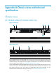
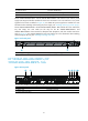
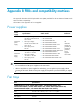
Figure 43 Rear panel
(1) Groundin
g
screw (auxiliary
g
roundin
g
point 2)
(2) Mana
g
ement Ethernet port
(3) Console port (4) Fan tray slot 1
(5) Fan tray slot 2
(6) Power supply slot 1
(7) Power supply slot 2 (8) LINK LED for the mana
g
ement Ethernet port
(9) ACT LED for the management Ethernet port (10) USB port
The HP 5900AF-48G-4XG-2QSFP+ and 5900AF-48G-4XG-2QSFP+ TAA switches come with the power
supply slots empty and the filler modules for the slots as accessories. You can install one or two power
supplies for the switch as needed. In Figure 43, t
wo 650W AC power supplies are installed. For more
information about installing and removing the power supply, see "Installing/removing a power supply."
The HP 5900AF-48G-4XG-2QSFP+ and 5900AF-48G-4XG-2QSFP+ TAA switches also come with the
fan tray slots empty. You must install two fan trays for the HP 5900AF-48G-4XG-2QSFP+ and
5900AF-48G-4XG-2QSFP+ TAA switches for adequate heat dissipation, and their models must be the
same. In Figure 43, t
wo LSWM1FANSC fan trays are installed. For more information about installing and
removing the fan tray, see "Installing/removing a fan tray."
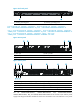
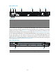
Figure 44 Left side panel
(1) Primary
g
roundin
g
point (2) Auxiliary
g
roundin
g
point 1