Hardware Reference Guide
© Copyright 2018, 2019 HP Development Company, L.P. Windows is either a registered trademark or trademark of Microsoft Corporation in the United States and/or other countries. The information contained herein is subject to change without notice. The only warranties for HP products and services are set forth in the express warranty statements accompanying such products and services. Nothing herein should be construed as constituting an additional warranty.
About This Book This guide provides basic information for upgrading the HP ProDesk Business PC. WARNING! Indicates a hazardous situation that, if not avoided, could result in serious injury or death. CAUTION: Indicates a hazardous situation that, if not avoided, could result in minor or moderate injury. IMPORTANT: Indicates information considered important but not hazard-related (for example, messages related to property damage).
iv About This Book
Table of contents 1 Product features ........................................................................................................................................... 1 Standard configuration features ........................................................................................................................... 1 Front panel components .......................................................................................................................................
Grounding methods ............................................................................................................................................. 45 Appendix C Computer operating guidelines, routine care and shipping preparation ............................................. 46 Computer operating guidelines and routine care ............................................................................................... 46 Optical drive precautions ................................................
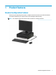
1 Product features Standard configuration features Features may vary depending on the model. For support assistance and to learn more about the hardware and software installed on your computer model, run the HP Support Assistant utility. NOTE: This computer model can be used in a tower orientation or a desktop orientation.
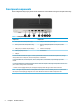
Front panel components Drive configuration may vary by model. Some models have a bezel blank covering the slim optical drive bay.
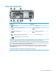
Rear panel components Table 1-2 Rear panel components Components Components 1 Audio-in jack 6 Optional port 2 Serial port (select products only) 7 USB ports (2) 3 RJ-45 (network) jack 8 USB SuperSpeed ports (4)** 4 Audio-out jack for powered audio devices* 9 Power cord connector 5 Dual-Mode DisplayPort monitor connectors (2) * When a device is plugged into the jack, a dialog box is displayed. Select the type of device that is connected.
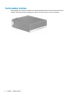
Serial number location Each computer has a unique serial number and a product ID number that are located on the exterior of the computer. Keep these numbers available for use when contacting customer service for assistance.
2 Hardware upgrades Serviceability features The computer includes features that make it easy to upgrade and service. A Torx T15 or flat-bladed screwdriver is needed for some of the installation procedures described in this chapter. Warnings and cautions Before performing upgrades be sure to carefully read all of the applicable instructions, cautions, and warnings in this guide.
Preparing for disassembly 1. Remove/disengage any security devices that prohibit opening the computer. 2. Remove all removable media, such as compact discs and USB flash drives, from the computer. 3. Turn off the computer properly through the operating system, and turn off any external devices. 4. Disconnect the power cord from the AC outlet and disconnect any external devices.
Replacing the computer access panel Be sure that the access panel release lever is locked into place, and then place the access panel on the computer (1) and slide the panel toward the front of the computer (2). The release lever will automatically move back to the left and secure the access panel.
Removing the front bezel 8 1. Prepare for disassembly. See Preparing for disassembly on page 6. 2. If the computer is on a stand, remove the computer from the stand and lay the computer down. 3. Remove the computer access panel. See Removing the computer access panel on page 6. 4. Lift up the four tabs on the top of the bezel (1), and then rotate the bezel off the chassis (2).
Removing a slim optical drive bezel blank On some models, a bezel blank covers the slim optical drive bay. Remove the bezel blank before installing an optical drive. To remove the bezel blank: 1. Prepare for disassembly. See Preparing for disassembly on page 6. 2. If the computer is on a stand, remove the computer from the stand and lay the computer down. 3. Remove the computer access panel. See Removing the computer access panel on page 6. 4. Remove the front bezel.
Replacing the front bezel Insert the four hooks on the bottom of the bezel into the rectangular holes on the chassis (1), and then rotate the top of the bezel onto the chassis (2) and snap it in place.
Removing and installing the optional front bezel dust filter Some models are equipped with an optional front bezel dust filter. You must periodically clean the dust filter so that the dust collected on the filter does not impede air flow through the computer. NOTE: The optional front bezel dust filter is available from HP. To remove, clean, and replace the dust filter: 1. Prepare for disassembly. See Preparing for disassembly on page 6. 2.
12 4. To replace the dust filter, press the filter firmly onto the front bezel at the tab locations shown below. 5. Reconnect the power cord and any external devices, and then turn on the computer.
Changing from desktop to tower orientation The Small Form Factor computer can be used in a tower orientation with an optional tower stand that can be purchased from HP. NOTE: To stabilize the computer in a tower orientation, HP recommends the use of the optional tower stand. 1. Prepare for disassembly. See Preparing for disassembly on page 6. 2. Orient the computer so that its right side is facing down and place the computer in the optional stand. 3.
System board connections Refer to the following illustration and table to identify the system board connectors for your model.
Upgrading system memory The computer comes with double data rate 4 synchronous dynamic random access memory (DDR4-SDRAM) dual inline memory modules (DIMMs). The memory sockets on the system board are populated with at least one preinstalled memory module. To achieve the maximum memory support, you can populate the system board with up to 64 GB of memory configured in a high-performing dual-channel mode.
DIMM and one 1 GB DIMM, and Channel B should be populated with the other two 1 GB DIMMs. With this configuration, 4 GB will run as dual-channel and 1 GB will run as single-channel. ● In any mode, the maximum operational speed is determined by the slowest DIMM in the system. IMPORTANT: You must disconnect the power cord and wait approximately 30 seconds for the power to drain before adding or removing memory modules.
3. Open both latches of the memory module socket (1), and insert the memory module into the socket (2). Press the module down into the socket, ensuring that the module is fully inserted and properly seated. Make sure the latches are in the closed position (3). NOTE: A memory module can be installed in only one way. Match the notch on the module with the tab on the memory socket. Populate the black DIMM sockets before the white DIMM sockets.
Removing or installing an expansion card The computer has one PCI Express ×4 expansion socket and one PCI Express ×16 expansion socket. NOTE: The PCI Express sockets support only low profile cards. You can install a PCI Express ×1, ×4, ×8, or ×16 expansion card in the PCI Express ×16 socket. For dual graphics card configurations, the first (primary) card must be installed in the PCI Express ×16 socket. To remove, replace, or add an expansion card: 1. Prepare for disassembly.
b. If you are removing a PCI Express ×4 card, hold the card at each end and carefully rock it back and forth until the connectors pull free from the socket. Lift the card straight up from the chassis (1) then away from the inside of the chassis (2) to remove it. Be sure not to scrape the card against other components.
c. If you are removing a PCI Express ×16 card, pull the retention arm on the back of the expansion socket away from the card (1) and carefully rock the card back and forth until the connectors pull free from the socket. Lift the card straight up from the chassis (2) then away from the inside of the chassis (3) to remove it. Be sure not to scrape the card against other components. 7. Store the removed card in anti-static packaging. 8.
9. To install a new expansion card, hold the card just above the expansion socket on the system board then move the card toward the rear of the chassis (1) so that the bottom of the bracket on the card slides into the small slot on the chassis. Press the card straight down into the expansion socket on the system board (2). NOTE: When installing an expansion card, press firmly on the card so that the whole connector is seated properly in the expansion card socket. 10.
12. Replace the computer access panel. 13. If the computer was on a stand, replace the stand. 14. Reconnect the power cord and any external devices, and then turn on the computer. 15. Lock any security devices that were disengaged when the access panel was removed. 16. Reconfigure the computer, if necessary. Drive positions Table 2-2 Drive positions Drive positions 1 3.5-inch hard drive bay 2 9.
Removing and installing drives When installing drives, follow these guidelines: ● The primary Serial ATA (SATA) hard drive must be connected to the dark blue primary SATA connector on the system board labeled SATA0. ● Connect an optical drive to the light blue SATA connector on the system board labeled SATA1.
Removing a 9.5 mm slim optical drive 1. Prepare for disassembly. See Preparing for disassembly on page 6. 2. If the computer is on a stand, remove the computer from the stand. 3. Remove the computer access panel. See Removing the computer access panel on page 6. 4. Disconnect the power cable (1) and data cable (2) from the rear of the optical drive. IMPORTANT: When removing the cables, pull the tab or connector instead of the cable itself to avoid damaging the cable. 5.
Installing a 9.5 mm slim optical drive 1. Prepare for disassembly. See Preparing for disassembly on page 6. 2. If the computer is on a stand, remove the computer from the stand. 3. Remove the computer access panel. See Removing the computer access panel on page 6. 4. If you are installing a slim optical drive in a bay covered by a bezel blank, remove the front bezel and then remove the bezel blank. See Removing a slim optical drive bezel blank on page 9 for more information. 5.
6. Slide the optical drive through the front bezel all the way into the bay (1) so that the latch on the rear of the drive locks into place (2). 7. Connect the power cable (1) and data cable (2) to the rear of the drive. 8. Connect the opposite end of the data cable to the light blue SATA connector on the system board labeled SATA1. NOTE: Refer to System board connections on page 14 for an illustration of the system board drive connectors. 9. Replace the front bezel if it was removed. 10.
12. Reconnect the power cord and any external devices, and then turn on the computer. 13. Lock any security devices that were disengaged when the access panel was removed. Removing and replacing a 3.5-inch hard drive NOTE: Before you remove the old hard drive, be sure to back up the data from the old hard drive so that you can transfer the data to the new hard drive. 1. Prepare for disassembly. See Preparing for disassembly on page 6. 2. If the computer is on a stand, remove the computer from the stand.
5. Pull the release lever next to the rear of the hard drive away from the drive (1). While pulling the release lever out, slide the drive forward until it stops, and then lift the drive up and out of the bay (2). 6. Install mounting screws on the sides of the hard drive using standard 6-32 silver-and-blue mounting screws. NOTE: If replacing a 3.5-inch hard drive, transfer the mounting screws from the old hard drive to the new hard drive. You can purchase extra mounting screws from HP.
● You can also install a 2.5-inch hard drive into a 3.5-inch drive bay using an adapter bracket similar to the example shown below. – Slide the 2.5-inch drive into the 3.5-inch adapter bracket. – Secure the drive to the bay adapter bracket by installing four black M3 adapter bracket screws through the underside of the bracket and into the drive.
– 7. 30 Install four 6-32 silver-and-blue mounting screws in the adapter bracket (two on each side of the bracket). Align the mounting screws with the slots on the chassis drive cage, press the hard drive down into the bay, and then slide the drive back until it stops and locks in place.
8. Connect the power cable (1) and the data cable (2) to the rear of the hard drive. NOTE: The data cable for the primary hard drive must be connected to the dark blue connector on the system board labeled SATA0 to avoid any hard drive performance problems. 9. Replace the computer access panel. 10. If the computer was on a stand, replace the stand. 11. Reconnect the power cord and any external devices, and then turn on the computer. 12.
32 6. Remove the drive cage. Push the release lever on the left side of the cage toward the cage (1), lift the left side of the cage away from the chassis (2), and then slide the right side of the cage out of the chassis (3). 7. To remove an M.2 SSD card, remove the grill (1), remove the bracket (2), remove the screw that secures the card (3), lift the end of the card away from the chassis (4), and then slide the card out of the system board connector (5).
8. To install an M.2 SSD card, slide the pins on the card into the system board connector while holding the card at approximately a 30° angle (1). Press the other end of the card toward the chassis (2), secure the card with the screw (3), replace the bracket (4), and then replace the grill (5). 9. Replace the drive cage. Slide the tabs on the right side of the drive cage into the slots on the chassis (1), and then press the left side of the drive cage down onto the chassis (2). 10.
14. Reconnect the power cord and any external devices, and then turn on the computer. 15. Lock any security devices that were disengaged when the access panel was removed. Installing a security lock The security locks displayed below and on the following pages can be used to secure the computer.
Padlock Installing a security lock 35
HP Business PC Security Lock V2 The HP PC Security Lock V2 is designed to secure all of the devices at your workstation. 36 1. Attach the security cable fastener to a desktop using the appropriate screws for your environment (screws not provided) (1), and then snap the cover onto the base of the cable fastener (2). 2. Loop the security cable around a stationary object.
3. Slide the security cable through the security cable fastener. 4. Pull the two scissor hands of the monitor lock apart and insert the lock into the security slot on the rear of the monitor (1), close the scissor hands together to secure the lock in place (2), and then slide the cable guide through the center of the monitor lock (3).
38 5. Slide the security cable through the security guide installed on the monitor. 6. Attach the accessory cable fastener to a desktop using the appropriate screw for your environment (screw not provided) (1), and then place the accessory cables into the base of the fastener (2).
7. Slide the security cable through the holes in the accessory cable fastener. 8. Screw the lock to the chassis using the screw provided.
9. Insert the plug end of the security cable into the lock (1) and push the button in to engage the lock (2). Use the key provided to disengage the lock. 10. When you have completed all steps, all of the devices at your workstation will be secured.
A Battery replacement The battery that comes with the computer provides power to the real-time clock. When replacing the battery, use a battery equivalent to the battery originally installed in the computer. The computer comes with a 3-volt lithium coin cell battery. WARNING! The computer contains an internal lithium manganese dioxide battery. There is a risk of fire and burns if the battery is not handled properly. To reduce the risk of personal injury: Do not attempt to recharge the battery.
b. Slide the replacement battery into position, positive side up. The battery holder automatically secures the battery in the proper position. Type 2 a. 42 To release the battery from its holder, squeeze the metal clamp that extends above one edge of the battery (1). When the battery pops up, lift it away from the holder (2).
b. To insert the new battery, slide one edge of the replacement battery under the lip of the holder with the positive side up (1). Push the other edge down until the clamp snaps over the other edge of the battery (2). Type 3 a. Pull back the clip (1) that is holding the battery in place, and remove the battery (2). b. Insert the new battery and position the clip back into place. NOTE: After the battery has been replaced, use the following steps to complete this procedure. 9.
11. Reconnect the power cord and any external devices, and then turn on the computer. 12. Reset the date and time, your passwords, and any special system setups using Computer Setup. 13. Lock any security devices that were disengaged when the computer access panel was removed.
B Electrostatic discharge A discharge of static electricity from a finger or other conductor may damage system boards or other staticsensitive devices. This type of damage may reduce the life expectancy of the device. Preventing electrostatic damage To prevent electrostatic damage, observe the following precautions: ● Avoid hand contact by transporting and storing products in static-safe containers. ● Keep electrostatic-sensitive parts in their containers until they arrive at static-free workstations.
C Computer operating guidelines, routine care and shipping preparation Computer operating guidelines and routine care Follow these guidelines to properly set up and care for the computer and monitor: 46 ● Keep the computer away from excessive moisture, direct sunlight, and extremes of heat and cold. ● Operate the computer on a sturdy, level surface. Leave a 10.2-cm (4-inch) clearance on all vented sides of the computer and above the monitor to permit the required airflow.
Optical drive precautions Be sure to observe the following guidelines while operating or cleaning the optical drive. Operation ● Do not move the drive during operation. This may cause it to malfunction during reading. ● Avoid exposing the drive to sudden changes in temperature, as condensation may form inside the unit. If the temperature suddenly changes while the drive is on, wait at least one hour before you turn off the power. If you operate the unit immediately, it may malfunction while reading.
D Accessibility Accessibility HP is working to weave diversity, inclusion and work/life into the fabric of our company, so it is reflected in everything we do. Here are some examples of how we are putting differences to work to create an inclusive environment focused on connecting people to the power of technology throughout the world. Finding the technology tools you need Technology can unleash your human potential.
HP is a founding member, and we joined to participate with other organizations to advance the field of accessibility. This commitment supports our company’s accessibility goal of designing, producing, and marketing products and services that can be effectively used by people with disabilities. IAAP will make our profession strong by globally connecting individuals, students, and organizations to learn from one another. If you are interested in learning more, go to http://www.accessibilityassociation.
● Assistive Technologies sorted by impairment type ● Assistive Technologies sorted by product type ● Assistive Technology vendors with product descriptions ● Assistive Technology Industry Association (ATIA) Standards and legislation Standards Section 508 of the Federal Acquisition Regulation (FAR) standards was created by the US Access Board to address access to information and communication technology (ICT) for people with physical, sensory, or cognitive disabilities.
● United Kingdom ● Australia ● Worldwide United States Section 508 of the Rehabilitation Act specifies that agencies must identify which standards apply to the procurement of ICT, perform market research to determine the availability of accessible products and services, and document the results of their market research. The following resources provide assistance in meeting Section 508 requirements: ● www.section508.gov ● Buy Accessible The U.S.
Europe EU Mandate 376 ETSI Technical Report ETSI DTR 102 612: "Human Factors (HF); European accessibility requirements for public procurement of products and services in the ICT domain (European Commission Mandate M 376, Phase 1)" has been released.
Useful accessibility resources and links The following organizations may be good resources for information about disabilities and age-related limitations. NOTE: This is not an exhaustive list. These organizations are provided for informational purposes only. HP assumes no responsibility for information or contacts you may encounter on the Internet. Listing on this page does not imply endorsement by HP.
Contacting support NOTE: ● Customers who are deaf or hard of hearing that have questions about technical support or accessibility of HP products: – ● 54 Support is in English only. Use TRS/VRS/WebCapTel to call (877) 656-7058 Monday through Friday, 6 a.m. to 9 p.m. Mountain Time. Customers with other disabilities or age-related limitations who have questions about technical support or accessibility of HP products, choose one of the following options: – Call (888) 259-5707 Monday through Friday, 6 a.
Index A access panel removal 6 replacement 7 accessibility 48 accessibility needs assessment assistive technology (AT) finding 49 purpose 48 AT (assistive technology) finding 49 purpose 48 B battery replacement 49 41 C computer operating guidelines 46 customer support, accessibility 54 D disassembly, preparation 6 drives cable connections 23 installation 23 locations 22 dust filter 11 E electrostatic discharge, preventing damage 45 expansion card installation 18 removal 18 F front bezel blank removal 9 r