Hardware Reference Guide
© Copyright 2018, 2019 HP Development Company, L.P. Windows is either a registered trademark or trademark of Microsoft Corporation in the United States and/or other countries. The information contained herein is subject to change without notice. The only warranties for HP products and services are set forth in the express warranty statements accompanying such products and services. Nothing herein should be construed as constituting an additional warranty.
Safety warning notice WARNING! To reduce the possibility of heat-related injuries or of overheating the computer, do not place the computer directly on your lap or obstruct the computer air vents. Use the computer only on a hard, flat surface. Do not allow another hard surface, such as an adjoining optional printer, or a soft surface, such as pillows or rugs or clothing, to block airflow.
iv Safety warning notice
About This Guide This guide provides basic information for upgrading the HP ProDesk Business PC. WARNING! Indicates a hazardous situation that, if not avoided, could result in serious injury or death. CAUTION: Indicates a hazardous situation that, if not avoided, could result in minor or moderate injury. IMPORTANT: Indicates information considered important but not hazard-related (for example, messages related to property damage).
vi About This Guide
Table of contents 1 Product features ........................................................................................................................................... 1 Standard configuration features ........................................................................................................................... 1 Front panel components .......................................................................................................................................
Grounding methods ............................................................................................................................................. 42 Appendix C Computer operating guidelines, routine care and shipping preparation ............................................. 43 Computer operating guidelines and routine care ............................................................................................... 43 Optical drive precautions ................................................
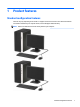
1 Product features Standard configuration features Features may vary depending on the model. For support assistance and to learn more about the hardware and software installed on your computer model, run the HP Support Assistant utility. NOTE: Refer to the illustration that most closely matches your computer.
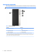
Front panel components Drive configuration may vary by model. Some models have a bezel blank covering the slim optical drive bay. NOTE: Refer to the illustration that most closely matches your computer.
Table 1-2 Front panel components Component Component 1 Slim optical drive (optional) 5 USB port with HP Sleep and Charge 2 Dual-state power button 6 USB port 3 Hard drive activity light 7 USB SuperSpeed ports (2)** 4 Audio-out (headphone)/Audio-in (microphone) combo jack* 8 Memory card reader * When a device is plugged into the combo jack, a dialog box is displayed. Select the type of device that is connected.
Rear panel components Table 1-3 Rear panel components Component Component 1 Audio-out jack for powered audio devices 6 Audio-in jack 2 DisplayPort monitor connector 7 RJ-45 (network) jack 3 VGA monitor connector 8 Serial port connector 4 USB SuperSpeed ports (2 or 4, depending on product) 9 Power cord connector 5 USB 2.0 ports (4) NOTE: An optional second serial port and an optional parallel port are available from HP.
Serial number location Each computer has a unique serial number and a product ID number that are located on the exterior of the computer. Keep these numbers available for use when contacting support for assistance.
2 Hardware upgrades Serviceability features The computer includes features that make it easy to upgrade and service. A Torx T15 or flat-bladed screwdriver is needed for many of the installation procedures described in this chapter. Warnings and cautions Before performing upgrades be sure to carefully read all of the applicable instructions, cautions, and warnings in this guide.
IMPORTANT: Regardless of the power-on state, voltage is always present on the system board as long as the system is plugged into an active AC outlet. You must disconnect the power cord to avoid damage to the internal components of the computer.
Removing the computer access panel 8 1. Prepare the computer for disassembly. See Preparing for disassembly on page 6. 2. Loosen the thumbscrew (1) on the rear of the computer and then slide the panel back (2) and lift if off the computer (3).
Replacing the computer access panel Place the panel on the computer (1), slide it forward (2), and then tighten the thumbscrew (3) to secure the panel in place.
Removing the front bezel 10 1. Prepare the computer for disassembly. See Preparing for disassembly on page 6. 2. Remove the computer access panel. See Removing the computer access panel on page 8. 3. Lift up the three tabs on the side of the bezel (1), and then rotate the bezel off the chassis (2).
Removing an optical drive bezel blank On some models, there is a bezel blank covering the slim optical drive bay. Remove the bezel blank before installing an optical drive. To remove the bezel blank: 1. Prepare the computer for disassembly. See Preparing for disassembly on page 6. 2. Remove the computer access panel and front bezel. See Removing the computer access panel on page 8 and Removing the front bezel on page 10. 3.
Replacing the front bezel Insert the three hooks on the bottom edge of the bezel into the rectangular holes on the chassis (1), and then rotate the top side of the bezel onto the chassis (2) and snap it into place.
System board connectors Refer to the following illustration and table to identify the system board connectors for your model. Table 2-1 System board connectors No.
Upgrading system memory The computer comes with double data rate 4 synchronous dynamic random access memory (DDR4-SDRAM) dual inline memory modules (DIMMs). The memory sockets on the system board are populated with at least one preinstalled memory module. To achieve the maximum memory support, you can populate the system board with up to 32 GB of memory configured in a high-performing dual-channel mode.
DIMM and one 1 GB DIMM, and Channel B should be populated with the other two 1 GB DIMMs. With this configuration, 4 GB will run as dual-channel and 1 GB will run as single-channel. ● In any mode, the maximum operational speed is determined by the slowest DIMM in the system. IMPORTANT: You must disconnect the power cord and wait approximately 30 seconds for the power to drain before adding or removing memory modules.
3. Open both latches (1) of the memory module socket and insert the memory module into the socket (2). Press the module down into the socket, ensuring that the module is fully inserted and properly seated. Make sure the latches are in the closed position (3). NOTE: A memory module can be installed in only one way. Match the notch on the module with the tab on the memory socket. Populate the black DIMM sockets before the white DIMM sockets.
3. Rotate the slot cover release latch to the open position. 4. Locate the correct vacant expansion socket on the system board and the corresponding expansion slot on the back of the computer chassis. 5. Before installing an expansion card, remove the expansion slot cover or the existing expansion card. NOTE: Before removing an installed expansion card, disconnect any cables that may be attached to the expansion card. a.
b. 18 If you are removing a PCI Express ×1 card, hold the card at each end and carefully rock it back and forth until the connectors pull free from the socket. Lift the card (1) straight up then away from the inside of the chassis (2) to remove it. Be sure not to scrape the card against other components.
c. If you are removing a PCI Express ×16 card, pull the retention arm on the back of the expansion socket away from the card and carefully rock the card back and forth until the connectors pull free from the socket. Lift the card straight up then away from the inside of the chassis to remove it. Be sure not to scrape the card against other components. 6. Store the removed card in anti-static packaging. 7.
8. To install a new expansion card, hold the card just above the expansion socket on the system board then move the card toward the rear of the chassis (1) so that the bottom of the bracket on the card slides into the small slot on the chassis. Press the card straight down into the expansion socket on the system board (2). NOTE: When installing an expansion card, press firmly on the card so that the whole connector seats properly in the expansion card socket. 9.
11. Replace the computer access panel. 12. Reconnect the power cord and any external devices, and then turn on the computer. 13. Lock any security devices that were disengaged when the computer access panel was removed. 14. Reconfigure the computer, if necessary. Drive positions Table 2-2 Drive positions Component 1 5.25-inch half-height hard drive bay 2 5.25-inch half-height hard drive bay 3 9.5 mm slim optical drive bay 4 3.
Removing and installing drives When installing drives, follow these guidelines: ● The primary Serial ATA (SATA) hard drive must be connected to the dark blue primary SATA connector on the system board labeled SATA0. ● Connect secondary hard drives and optical drives to one of the light blue SATA connectors on the system board (labeled SATA1 and SATA2).
3. Disconnect the power cable (1) and data cable (2) from the rear of the optical drive. IMPORTANT: When removing the cables, pull the tab or connector instead of the cable itself to avoid damaging the cable. 4. Press the release lever on the back of the drive (1), and then slide the drive through the front bezel (2).
Installing a 9.5 mm slim optical drive 24 1. Prepare the computer for disassembly. See Preparing for disassembly on page 6. 2. Remove the computer access panel. See Removing the computer access panel on page 8. 3. If you are installing a slim optical drive in a bay covered by a bezel blank, remove the front bezel and then remove the bezel blank. See Removing an optical drive bezel blank on page 11 for more information. 4. Follow the instructions for removing the optical drive if one was installed.
6. Slide the optical drive through the front bezel (1) all the way into the bay so that the green latch locks onto the chassis frame (2). 7. Connect the power cable (1) and data cable (2) to the rear of the optical drive. 8. If installing a new drive, connect the opposite end of the data cable to one of the light blue SATA connectors (labeled SATA1 and SATA2) on the system board. 9. Replace the front bezel if it was removed. 10. Replace the computer access panel.
11. Reconnect the power cord and any external devices, and then turn on the computer. 12. Lock any security devices that were disengaged when the access panel was removed. Removing a 3.5-inch hard drive NOTE: Before you remove the old hard drive, be sure to back up the data from the old hard drive so that you can transfer the data to the new hard drive. 26 1. Prepare the computer for disassembly. See Preparing for disassembly on page 6. 2. Remove the computer access panel.
4. Remove the mounting screws (1) and pull the drive up and out of the cage (2). Installing a 3.5-inch hard drive 1. Prepare the computer for disassembly. See Preparing for disassembly on page 6. 2. Remove the computer access panel. See Removing the computer access panel on page 8. 3. Lower the drive into the cage and slide it into position (1), and then use the mounting screws that were removed from the old drive to install the new one (2).
4. Connect the power cable (1) and data cable (2) to the rear of the hard drive. 5. If installing a new drive, connect the opposite end of the data cable to the appropriate system board connector. NOTE: You must connect the primary hard drive data cable to the dark blue connector labeled SATA0 to avoid any hard drive performance problems. If you are adding a second hard drive, connect the data cable to one of the light blue SATA connectors. 6. Replace the computer access panel. 7.
3. Disconnect the power cable (1) and data cable (2) from the rear of the hard drive. 4. Remove the three 6-32 mounting screws (1) and slide the drive out of the bay (2). Installing a 2.5-inch hard drive 1. Prepare the computer for disassembly. See Preparing for disassembly on page 6. 2. Remove the computer access panel. See Removing the computer access panel on page 8.
3. Slide the drive into the drive bay (1) and install the three 6-32 mounting screws (2) to secure the drive in place. NOTE: When replacing a hard drive, use the three 6-32 mounting screws that were removed from the old drive to install the new one. 30 4. Connect the power cable (1) and data cable (2) to the rear of the hard drive. 5. If installing a new drive, connect the opposite end of the data cable to the appropriate system board connector.
NOTE: You must connect the primary hard drive data cable to the dark blue connector labeled SATA0 to avoid any hard drive performance problems. If you are adding a second hard drive, connect the data cable to one of the light blue SATA connectors. 6. Replace the computer access panel. 7. Reconnect the power cord and any external devices, and then turn on the computer. 8. Lock any security devices that were disengaged when the access panel was removed.
Padlock HP Business PC Security Lock V2 1. 32 Attach the security cable fastener to a desktop using the appropriate screws for your environment (screws not provided) (1), and then snap the cover onto the base of the cable fastener (2).
2. Loop the security cable around a stationary object. 3. Slide the security cable through the security cable fastener.
34 4. Pull the two scissor hands of the monitor lock apart and insert the lock into the security slot on the rear of the monitor (1), close the scissor hands together to secure the lock in place (2), and then slide the cable guide through the center of the monitor lock (3). 5. Slide the security cable through the security guide installed on the monitor.
6. Attach the accessory cable fastener to a desktop using the appropriate screw for your environment (screw not provided) (1), and then place the accessory cables into the base of the fastener (2). 7. Slide the security cable through the holes in the accessory cable fastener.
36 8. Remove the thumbscrew from the rear of the chassis and screw the lock to the chassis in the thumbscrew hole. 9. Insert the plug end of the security cable into the lock (1) and push the button (2) in to engage the lock. Use the key provided to disengage the lock.
10. When you have completed all steps, all of the devices at your workstation will be secured.
A Battery replacement The battery installed on the computer provides power to the real-time clock. When replacing the battery, use a battery equivalent to the battery originally installed on the computer. The computer has a 3-volt lithium coin cell battery installed. WARNING! The computer contains an internal lithium manganese dioxide battery. There is a risk of fire and burns if the battery is not handled properly. To reduce the risk of personal injury: Do not attempt to recharge the battery.
b. Slide the replacement battery into position, positive side up. The battery holder automatically secures the battery in the proper position. Type 2 a. To release the battery from its holder, squeeze the metal clamp (1) that extends above one edge of the battery. When the battery (2) pops up, lift it out.
b. To insert the new battery, slide one edge of the replacement battery under the lip of the holder (1) with the positive side up. Push the other edge down until the clamp snaps over the other edge of the battery (2). Type 3 a. Pull back on the clip (1) that is holding the battery in place, and remove the battery (2). b. Insert the new battery and position the clip back into place. NOTE: After the battery has been replaced, use the following steps to complete this procedure. 40 5.
7. Reset the date and time, your passwords, and any special system setups using Computer Setup. 8. Lock any security devices that were disengaged when the computer access panel was removed.
B Electrostatic discharge A discharge of static electricity from a finger or other conductor may damage system boards or other staticsensitive devices. This type of damage may reduce the life expectancy of the device. Preventing electrostatic damage To prevent electrostatic damage, observe the following precautions: ● Avoid hand contact by transporting and storing products in static-safe containers. ● Keep electrostatic-sensitive parts in their containers until they arrive at static-free workstations.
C Computer operating guidelines, routine care and shipping preparation Computer operating guidelines and routine care Follow these guidelines to properly set up and care for the computer and monitor: ● Keep the computer away from excessive moisture, direct sunlight, and extremes of heat and cold. ● Operate the computer on a sturdy, level surface. Leave a 10.2-cm (4-inch) clearance on all vented sides of the computer and above the monitor to permit the required airflow.
Optical drive precautions Be sure to observe the following guidelines while operating or cleaning the optical drive. Operation ● Do not move the drive during operation. This may cause it to malfunction during reading. ● Avoid exposing the drive to sudden changes in temperature, as condensation may form inside the unit. If the temperature suddenly changes while the drive is on, wait at least one hour before you turn off the power. If you operate the unit immediately, it may malfunction while reading.
D Accessibility HP designs, produces, and markets products and services that can be used by everyone, including people with disabilities, either on a stand-alone basis or with appropriate assistive devices. Supported assistive technologies HP products support a wide variety of operating system assistive technologies and can be configured to work with additional assistive technologies. Use the Search feature on your device to locate more information about assistive features.
Index A access panel removal 8 replacement 9 accessibility 45 computer access panel 9 drive cables 22 expansion card 16 memory 14 optical drive 24 B battery replacement L locks cable lock 31 HP Business PC Security Lock padlock 32 38 C computer operating guidelines 43 D drives cable connections 22 installation 22 locations 21 M memory installation 14 socket population E electrostatic discharge, preventing damage 42 expansion card installation 16 removal 16 F front bezel blank removal 11 removal 10