6-Port SATA RAID Controller User Guide Part number: 377602-003 Third edition: May 2006
Legal notices © Copyright 2004, 2006 Hewlett-Packard Development Company, L.P. The information contained herein is subject to change without notice. The only warranties for HP products and services are set forth in the express warranty statements accompanying such products and services. Nothing herein should be construed as constituting an additional warranty. HP shall not be liable for technical or editorial errors or omissions contained herein.
Contents 1 Board components and features Controller specifications and attributes........................................................................................................ 4 2 Installation and configuration procedures Overview of the installation process ........................................................................................................... 5 Installing the controller and drives ...............................................................................................
1 Board components and features Figure 1-1 6-Port SATA RAID Controller 1 Internal SATA port 0 3 Flash jumper 2 Internal SATA port 5 4 I2C connector Controller specifications and attributes Table 1-1 Controller specifications and attributes Ambient temperature 0°C to 50°C (forced airflow is recommended, but not required) Relative humidity 10% to 90%, noncondensing Altitude Up to 3,000 meters Ripple and noise 50 mV peak-to-peak (max) DC voltage 5 V ± 0.5 V Maximum current 2.
2 Installation and configuration procedures Overview of the installation process 1. Install and configure the controller and hard drives. For details, see “Installing the controller and drives” on page 5. The maximum supported size of the logical drive on this controller is 2 TB. NOTE: Select drives of equal capacity and performance. Otherwise, the array tends to be limited in capacity and performance to that of the smallest and slowest drive.
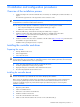
7. Attach the other end of the I2C able to the connector on the internal drive cage backplane board (2). Figure 2-1 8. Install drives in the internal SATA drive bay of the server, if necessary. The 6-Port SATA RAID Controller can support logical drives of up to 2 TB capacity. NOTE: To determine the number of drives required for a particular RAID level, see page 17. 9.
Assigning the boot controller NOTE: If the server will contain two or more bootable controllers, read this section. Otherwise, omit this section. The 6-Port SATA RAID controller supports bootable drives and arrays. The default setting of the controller and system setup usually allows you to install and boot from either a hard drive connected to the motherboard, or from a drive or array connected to the controller.
13. On the next screen, respond as follows: Table 2-1 Entries for array properties Property line displayed Entry or selection Array type Select the RAID level, and the press the Enter key. Array label Type a name, and then press the Enter key. Array size Press the Enter key, and then press the Enter key again to use the default granularity of GB. Stripe size Press the Enter key. Read caching Press the Enter key. Write caching Press the Enter key. Create RAID Press the Enter key.
Appendix A: Electrostatic discharge Preventing electrostatic discharge To prevent damaging the system, be aware of the precautions you must follow when setting up the system or handling parts. A discharge of static electricity from a finger or other conductor may damage system boards or other static-sensitive devices. This type of damage may reduce the life expectancy of the device. To prevent electrostatic damage: • Avoid hand contact by transporting and storing products in static-safe containers.
Appendix B: Regulatory compliance notices Federal Communications Commission notice Part 15 of the Federal Communications Commission (FCC) Rules and Regulations has established Radio Frequency (RF) emission limits to provide an interference-free radio frequency spectrum. Many electronic devices, including computers, generate RF energy incidental to their intended function and are, therefore, covered by these rules.
For questions regarding this FCC declaration, contact us by mail or telephone: • Hewlett-Packard Company P. O. Box 692000, Mail Stop 510101 Houston, Texas 77269-2000 • 1-281-514-3333 To identify this product, refer to the part, series, or model number found on the product. Modifications The FCC requires the user to be notified that any changes or modifications made to this device that are not expressly approved by Hewlett-Packard Company may void the user’s authority to operate the equipment.
Japanese notice Korean notices Class A Equipment Class B Equipment Appendix B: Regulatory compliance notices 12
Appendix C: Using the RAID Configuration Utility The RAID Configuration Utility is loaded on the controller ROM. The utility is used to create, configure, and manage arrays, and make arrays bootable. It is also used to initialize and rescan drives. To run the utility, press Ctrl+A when prompted by the following message during system startup: Press for Adaptec RAID Configuration Utility Creating arrays 1. Power down the computer, and then restart it.
. 15. Select the method by which you want the array to be created. • Build/Verify conducts a background initialization on the array. The array is available immediately, although performance is degraded. • Quick Init also enables the array to be available immediately, without any ongoing background controller activity. • Clear conducts a foreground initialization on the array. All blocks in the array are set to zero, and the array is not accessible until the task is complete. Select Done.
4. Press the Enter key. The following message appears: Warning!! Deleting will erase all the data from the array. Do you still want to continue? (Yes/No): 5. Select Yes to delete the array, or No to return to the previous menu. 6. In the Array Properties dialog box, select Delete again, and then press the Enter key. 7. Press the Esc key to return to the previous menu. Managing failover drive assignments To assign a hotspare to an array: 1.
Rescanning drives 1. Restart the computer. 2. When the appropriate prompt appears, press Ctrl+A to access the RAID Configuration Utility. 3. From the RAID Configuration Utility menu, select Array Configuration Utility. 4. Select Rescan Drives.
Appendix D: About RAID A Redundant Array of Independent Disk (RAID) provides better performance and reliability from combinations of drives than is possible with the same total storage space without RAID. This Appendix describes the various RAID levels supported by the 6-Port SATA RAID controller. The following table shows the number of drives needed and supported for the controller according to RAID level.
RAID 1 A RAID 1 array is created by copying, or mirroring, all data from one drive onto a second drive. This mirroring provides redundancy, ensuring that if one drive fails no data is lost. However, redundancy also means that only half the total capacity is available. Figure 4 A RAID 1 array A RAID 1 array has no write performance advantage over a simple volume configuration, but it has improved read performance because the drives share read load equally.
RAID 10 This dual-level RAID type is created by using two or more equal-sized RAID 1 arrays to create a RAID 0 array. Both read and write performance are improved because array striping occurs. However, the performance improvement requires that additional storage space be used because the arrays are mirrored.
RAID 50 This dual-level RAID type is created by using two or more equal-sized RAID 5 arrays to create a RAID 0 array. The top level RAID 0 array shares the load among the second-level RAID 5 arrays, improving both read and write performance. Parity (Pan or Pbn), used in the second level RAID 5 arrays, provides efficient redundancy.
Glossary activity See task. array A logical disk created from available space and made up of one or more partitions on one or more physical disks. Arrays are typically used to provide data redundancy or enhanced I/O performance. See also container, volume, spanned volume, and RAID signature. Also known as a container. array initialization See initialize. automatic failover See failover drive.
degraded A redundant array (for example, a RAID 1 array) in which one or more members have failed. The data is intact, but redundancy has been compromised. Any further failure would cause the array to fail and result in data loss. dirty data Data that has been written to a cache, but which has not been flushed out to its final destination. disk A nonremovable platter in a hard drive, or removable media used in a CD drive, floppy disk drive, or Zip drive.
impacted An impacted array is one which has been created, but for some reason the initial build operation did not complete. All member drives are present and operational, and all data written to the array is protected. To optimize the array, run a Verify with Fix task. initialize Process of preparing a disk for use by the controller. When a disk is initialized, the controller records the RAID signature on the disk. initialized array An array that is ready for data reads and writes.
redundant The ability of an array to maintain operability when one or more hardware failures occur. RAID 1 array is an example of a redundant array. In the event of a drive failure, redundant arrays can be restored to normal operation by replacing the failed drive and rebuilding the array. rescan Process of updating the current screen to show all currently available resources. segment Disk drive or portion of a disk drive used to create a logical device.
Index B E J board components, 4 boot controller, assigning, 7 bootable array, creating, 7 BSMI notice, 11 electrostatic discharge, 9 European Union regulatory notice, 11 Japanese notice, 12 F Korean notices, 12 Federal Communications Commission (FCC) notice, 10 flash jumper, location of, 4 R C cables, 11 Canadian notice, 11 controller attributes, 4 controller features, 4 controller specifications, 4 D G RAID levels supported, 17 regulatory compliance notices, 10 S grounding methods, 9 I decla