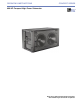
OPERATING INSTRUCTIONS CONCERT SERIES 600-HP Compact High-Power Subwoofer Keep these important operating instructions. Check www.meyersound.com for updates.
DECLARATION OF CONFORMITY ACCORDING TO ISO/IEC GUIDE 22 AND EN 45014 Manufacturer’s Name: Meyer Sound Laboratories Inc. Manufacturer’s Address: 2832 San Pablo Avenue Berkeley, CA 94702-2204, USA Declares that the products Product Name: 600-HP Product Options: All Conforms to the following Product Specifications Safety: IEC 60065: 2002 BS EN 60065: 2002 CSA C22.2 60065: 2003 UL 813: 1999 EMC: EN 55103-1: 1997 emission(1) EN 55103-2: 1997 immunity(2) This device complies with EN 55103-1 & -2.
SYMBOLS USED These symbols indicate important safety or operating features in this booklet and on the chassis: Dangerous voltages: risk of electric shock Important operating instructions Frame or chassis Protective earth ground Pour indiquer les risques résultant de tensions dangereuses Pour indequer important instructions Masse, châssis Terre de protection Zu die gefahren von gefährliche spanning zeigen Zu wichtige betriebsanweisung und unterhaltsanweisung zeigen Rahmen oder chassis Die schutze
SAFETY SUMMARY English - - - - - - To reduce the risk of electric shock, disconnect the loudspeaker from the AC mains before installing audio cable. Reconnect the power cord only after making all signal connections. Connect the loudspeaker to a two-pole, three-wire grounding mains receptacle. The receptacle must be connected to a fuse or circuit breaker. Connection to any other type of receptacle poses a shock hazard and may violate local electrical codes.
CONTENTS INTRODUCTION How to Use this Manual CHAPTER 1: Introducing the 600-HP Compact High-Power Subwoofer High Power and High Performance Versatile Configuring and Rigging Features & Benefits Applications CHAPTER 2: Power Requirements AC Power Voltage Requirements AC Power Distribution Current Requirements Power Connector Wiring Conventions Electrical Safety Issues 1 1 3 3 3 4 4 5 5 5 5 6 7 8 CHAPTER 3: Amplification and Audio 9 Audio Input 600-HP Interconnections Cabling 600-HP Limiting 600-HP Ampli
CHAPTER 7: QuickFly® Rigging and Ground-stacking Flying the 600-HP Subwoofer GuideALink™ Rigging Frame 600-HP to 600-HP Flown Ground-stacked 600-HP to MICA Flown Ground-stacked The MG-MICA Multipurpose Grid Flown Configuration Ground-Stacked Configuration The Optional MDTL-MICA Downtilt Link MCF-MICA Caster Frame MDB-600 Dolly Board APPENDIX A: Amplifier Replacement and Optional Rain Hood Using the Rain Hood (Weather-Protected Loudspeakers) Removing the HP-2/600 Amplifier Replacing the HP-2/600 Amplifier APPEN
INTRODUCTION INTRODUCTION TO THIS MANUAL These operating instructions provide important information about the form, features, function, and specifications of the 600-HP high-power subwoofer. In addition to power requirements and audio characteristics, fundamental system design, useful software tools, and array configurations for the 600-HP are discussed. Chapter 1: Introduction provides a general description of the 600-HP and its capabilities and functionality.
INTRODUCTION 2
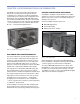
CHAPTER 1 CHAPTER 1: INTRODUCING THE 600-HP SUBWOOFER The 600-HP is a self-powered, high-output subwoofer that may be used in both flown and ground-stacked configurations. It is designed to rig directly with MICA™ compact high-power curvilinear array loudspeakers when fitted with the optional QuickFly MRF-600 rigging frame.
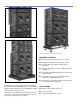
CHAPTER 1 Figure 1.3. Flown array with MICA loudspeakers and 600-HP subwoofers Figure 1.5.
CHAPTER 2 CHAPTER 2: POWER REQUIREMENTS Self-powered and highly portable, the 600-HP subwoofer incorporates advanced loudspeaker technology with equally advanced power capabilities. Understanding the 600-HP subwoofer’s power distribution, voltage and current requirements, as well as electrical safety issues, is critical to the safe and correct operation and deployment of the 600-HP subwoofer.
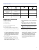
CHAPTER 2 NOTE: Refer to Appendix B for details on the 600-HP’s AC voltage requirements. After applying AC power, the proper operating voltage is automatically selected, but the system is muted. During the next three seconds the following events occur: 1. The primary fan turns on. 2. The main power supply slowly ramps on. 3. The green Active LED on the user panel lights up, indicating that the system is enabled and ready to pass audio signals.
CHAPTER 2 neutral (blue) CAUTION: In the unlikely event that the circuit breakers on the user panel trip (the white center buttons pop out), disconnect the AC power cable. Do not reset the breakers with the AC connected. Contact Meyer Sound for repair information. line (brown) ground (green/yellow) POWER CONNECTOR WIRING CONVENTIONS The 600-HP subwoofer requires a grounded outlet. It is very important that the system be properly grounded in order to operate safely and properly. Figures 2.2, 2.3, 2.
CHAPTER 2 ELECTRICAL SAFETY ISSUES Pay close attention to these important electrical and safety issues. CAUTION: Do not use a power cord adapter to drive the 600-HP subwoofer from a standard three-prong Edison outlet since that connector is rated for only 15 amps (NEMA 5-15R; 125 V AC max.). CAUTION: The 600-HP subwoofer requires a ground connection. Always use a grounded outlet and plug. TIP: Use the ring located on rear of the 600-HP subwoofer to provide strain relief for power and signal cables.
CHAPTER 3 CHAPTER 3: AMPLIFICATION AND AUDIO The 600-HP uses sophisticated amplification and protection circuitry to produce consistent and predictable results in any system design. This chapter will help you understand and harness the power of the 600-HP amplifier and audio systems. The rear panel of the 600-HP (Figure 3.1) provides AC connection, audio input and loop out. Use standard audio cables with XLR connectors for balanced signal sources.
CHAPTER 3 NOTE: Most source equipment is safe for driving loads no smaller than 10 times the source’s output impedance. For example an equalizer with a 150 Ohms output impedance should be able with drive a load of 1500 Ohms. TIP: If abnormal noises such as hum and popping are produced by the subwoofer, disconnect the audio cable from the subwoofer. If the noise stops, then most likely the problem is not with the subwoofer. Check the audio cable, source, and AC power for the source of the problem.
CHAPTER 3 TruPower limiting also eliminates power compression when the system is operated at high levels for extended periods, and extends the driver life cycle by controlling voice coil temperatures. The 600-HP’s left and right 15-inch cone drivers are powered by separate amplifier channels, each with a power detector but routed to one limiter; the limiter tracks both channels and uses the higher of the two values to engage.
CHAPTER 3 NOTE: In the highly unlikely event that the secondary fan does not keep the temperature below 85˚ C, the 600-HP automatically shuts down until AC power is removed and reapplied. If the 600-HP shuts down again after cooling and reapplying AC power, contact Meyer Sound for repair information. Despite the 600-HP’s filtering, extensive use or a dusty operating environment can allow dust to accumulate along the path of the airflow, preventing normal cooling.
CHAPTER 4 CHAPTER 4: RMS REMOTE MONITORING SYSTEM (OPTIONAL) The RMS communication module is standard in 600-HP subwoofers with the MRF-600 rigging frame installed and is optional in the other models, making use of Meyer Sound’s RMS remote monitoring system. RMS is a real-time networked monitoring system that connects Meyer Sound selfpowered loudspeakers with a Windows-based PC at the sound mix position or other desired location.
CHAPTER 4 Service Button USER INTERFACE Pressing the Service button will notify the corresponding loudspeaker display icon on the RMS screen. When used in combination with the Reset button, the card will be decommissioned from the network and the red Service LED will blink. The RMS software features an intuitive, graphical Windows user interface.
CHAPTER 5 CHAPTER 5: SYSTEM INTEGRATION USING 600-HP SUBWOOFERS WITH OTHER MEYER SOUND LOUDSPEAKERS It is often necessary to augment mid-high or full-range systems with subwoofers when higher SPL is needed, or the program content requires additional low-frequency energy (e.g., the reinforcement of popular music). The 600-HP subwoofer can achieve frequencies down in the 36 Hz range, extending the system response appreciably and increasing the acoustic power of the system in the lowest frequencies.
CHAPTER 5 The 600-HP subwoofers should be placed as close as possible to the other loudspeakers so that the relative distances between them are the same at all listening positions. NOTE: When 600-HP subwoofers are used with Concert Series or UltraSeries loudspeakers in their full-range configuration (e.g., looped audio or the same audio feed), their polarities should be the same if they are coplanar or near each other.
CHAPTER 5 NOTE: When driving Concert or UltraSeries loudspeakers from the Mid-Hi output of the LD-1A or LD-2 line driver, with the Lo-Cut filter engaged and the 600-HP subwoofers in their full-range configuration, a change of polarity on the Sub Output might be needed due to the phase shift caused by the high-pass filter at overlapping frequencies. Placing the subwoofers more than 4 feet apart may require reversing the polarities once again to compensate for the delay propagation.
CHAPTER 5 phase shift differences between the loudspeakers and the subwoofers. In addition, you should verify the delay time between channels. Some DSPs may develop channel-tochannel variations in delay when the DSP is near maximum throughput, which becomes more likely as the number of filters the DSP is using increases. NOTE: Avoid using filters higher than 2nd order. The additional phase shift introduced deteriorates the impulse response and higher roll-off does not improve crossover interaction.
CHAPTER 6 CHAPTER 6: SYSTEM DESIGN AND INTEGRATION TOOLS Meyer Sound offers two comprehensive tools to assist you with the acoustical and functional requirements of system design and optimization. This chapter introduces you to MAPP Online Pro, Meyer Sound’s powerful online acoustical prediction tool, and SIM 3, a robust instrumentation package for system measurement, analysis, and more.
CHAPTER 6 The key to MAPP Online Pro’s value is the accuracy of its predictions. Performance predictions for each Meyer Sound loudspeaker found in MAPP Online Pro are based on a model of that product built from 360 1/48th-octave–band measurements taken with a SIM audio analyzer in our anechoic chamber. The extreme consistency found from cabinet to cabinet in Meyer Sound products guarantees that the predictions MAPP Online Pro makes from this highresolution data will closely match actual performance.
CHAPTER 7 CHAPTER 7: QUICKFLY RIGGING AND GROUND-STACKING When fitted with the optional MRF-600 rigging frame, the 600-HP may be flown alone or with MICA curvilinear array loudspeakers. It may also be ground-stacked in vertical and horizontal arrays using this version or the versions with handles or plain side panels.
CHAPTER 7 The front links may be set in two different positions: ■ 0°: This is the standard position (left figure) and it is used to achieve a 0-degree angle between adjacent 600-HP enclosures. ■ +3°: The main purpose for this extended position (right figure) is to curve a 600-HP stand-alone array that is flown next to a MICA array, both for appearance and to keep the subwoofer array from blocking the horizontal high-frequency coverage from the MICA enclosures lower in the array.
CHAPTER 7 This rigging capability allows all of the 600-HPs to be positioned at 0 degrees in relation to each other and to the MGMICA grid, while introducing the desired angle to the MICA array using the GuideALinks on the lowest 600-HP enclosure — without needing to adjust the angle of the remaining 600-HPs or the MG-MICA grid. Table 7.3. 600-HP Link Positions to MICA (flown) Table 7.4. MICA Link Positions to 600-HP (ground-stacked) Rear Front Angle for MICA 0 0 0° 0.5 0 0.
CHAPTER 7 THE MG-MICA MULTIPURPOSE GRID Flown Configuration The MG-MICA multipurpose grid (Figure 7.7) allows multiple 600-HP subwoofers fitted with MRF-600 rigging frames and/or MICA compact high-power curvilinear array loudspeakers to be flown or ground-supported in numerous configurations. The subwoofer’s MRF-600 GuideALink rigging is directly compatible with MICA, and links to both the grid and MICA enclosures using the same slots and pins.
CHAPTER 7 Ground-Stacked Configuration The MG-MICA ground-stacked pockets receive the 600-HP links directly (Figure 7.9). Many combinations are possible; the most common are listed in the table below. Table 7.5. 600-HP Link Positions to MG-MICA Grid (ground-stacked) Rear Front Angle for 600-HP with respect to the MG-MICA grid -3 0 0.5° uptilt 0 0 2.5° downtilt 6 +3 0.5° uptilt Figure 7.10.
����������������� ���������������������������������������������������������� ��������������������������������������������������� CHAPTER 7 �������������� ��������� ��������������� �������� Whether you’re deploying or striking an array, the MCFMICA can temporarily support its weight — making it easy to assemble or disassemble the array in stacks of up to three 600-HPs.
CHAPTER 7 CAUTION: Avoid using the 600-HP front or rear link in the extended position (+3 in front and any setting other than 0 in the rear) when transporting the subwoofers on the MCF-MICA to avoid tipping over the stack. The MCF-MICA also allows 600-HP subwoofers to be supported in a ground-stacked configuration. CAUTION: When using the MCF-MICA caster frame to ground-stack 600-HP subwoofers, make sure all four caster wheels are blocked to prevent the stack from rolling away.
CHAPTER 7 In addition to transport, the MDB-600 supports 600-HP subwoofers in a ground-stacked configuration. CAUTION: When using the MDB-600 dolly board to ground-stack 600-HP subwoofers, make sure all four caster wheels are blocked to prevent the stack from rolling away. Other rigging accessories as well as a range of rugged protective transport covers are also available. For more information, please visit www.meyersound.com. Figure 7.17.
APPENDIX A APPENDIX A: AMPLIFIER REPLACEMENT AND OPTIONAL RAIN HOOD USING THE RAIN HOOD (WEATHER-PROTECTED LOUDSPEAKERS) If your 600-HP loudspeaker was ordered with optional weather protection, a rain hood is provided to protect the loudspeaker’s electronics from direct exposure to rainfall. The rain hood frame will be pre-installed. Before using the 600-HP loudspeaker, install the rain hood as described in the following procedure. 1.
APPENDIX A 30
APPENDIX B APPENDIX B: 600-HP SPECIFICATIONS ACOUSTICAL Operating frequency range 36 Hz - 150 Hz Note: Recommended maximum operating frequency range. Response depends upon loading conditions and room acoustics. Frequency response 39 Hz - 130 Hz ±4 dB Note: Free field, measured with 1/3 octave frequency resolution at 4 meters. Phase response 46 Hz - 120 Hz ±30° Maximum peak SPL 138 dB Note: Measured with music, referred to 1 meter, half-space loading.
APPENDIX B AC POWER AC power connector 250 V NEMA L6-20 (twist lock), IEC 309 male inlet, PowerCon, or VEAM Voltage selection Automatic, two ranges, each with high-low voltage tap � Safety agency rated operating voltage 95 V AC - 125 V AC; 208 V AC - 235 V AC; 50/60 Hz Turn on/turn off points 85 V AC - 134 V AC; 165 V AC - 264 V AC; 50/60 Hz Current Draw Idle current 0.64 A rms (115 V AC); 0.32 A rms (230 V AC); 0.85 A rms (100 V AC) Max. long-term continuous current (>10 sec) 8.
Meyer Sound Laboratories Inc. 2832 San Pablo Avenue Berkeley, CA 94702 www.meyersound.com T: +1 510 486.1166 F: +1 510 486.8356 © 2006 Meyer Sound Laboratories Inc. 05.149.005.