HP 6400/8400 Enterprise Virtual Array User Guide Abstract This document describes the components and operation of the HP 6400/8400 Enterprise Virtual Array.
© Copyright 2009, 2013 Hewlett-Packard Development Company, L.P. The information contained herein is subject to change without notice. The only warranties for HP products and services are set forth in the express warranty statements accompanying such products and services. Nothing herein should be construed as constituting an additional warranty. HP shall not be liable for technical or editorial errors or omissions contained herein.
Contents 1 EVA6400/8400 hardware..........................................................................9 M6412A disk enclosures............................................................................................................9 Enclosure layout...................................................................................................................9 I/O modules.....................................................................................................................
Using FATA disk drives........................................................................................................34 Using solid state disk drives.................................................................................................34 QLogic HBA speed setting..................................................................................................34 EVA6400/8400 host port negotiates to incorrect speed.........................................................
Updating the AlphaServer console code, Integrity Server console code, and Fibre Channel FCA firmware...........................................................................................................................53 Verifying the Fibre Channel adapter software installation........................................................53 Console LUN ID and OS unit ID...........................................................................................53 Adding OpenVMS hosts...........................
Support and other resources......................................................................80 Contacting HP........................................................................................................................80 Subscription service............................................................................................................80 Documentation feedback....................................................................................................
Greek recycling notice........................................................................................................92 Hungarian recycling notice.................................................................................................92 Italian recycling notice........................................................................................................92 Latvian recycling notice......................................................................................................
Windows Server (32-bit) configuration................................................................................119 Requirements..............................................................................................................119 HBA configuration.......................................................................................................120 Risks..........................................................................................................................
1 EVA6400/8400 hardware The EVA6400/8400 contains the following hardware components: • HSV controllers—Contains power supplies, cache batteries, fans, and an operator control panel (OCP) • Fibre Channel disk enclosure—Contains disk drives, power supplies, fans, midplane, and I/O modules • Fibre Channel Arbitrated Loop cables—Provides connectivity to the HSV controllers and the Fibre Channel disk enclosures • Rack—Several free standing racks are available M6412A disk enclosures The M6412A disk enclos
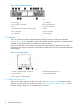
Figure 3 Disk enclosure rear view 1. Power supply 1 7. I/O module B 2. Power supply 1 status LED 8. Rear UID push button 3. Fan 1 9. Enclosure status LEDs 4. Enclosure product number and serial number 10. Fan 2 5. Fan 1 status LED 11. Power push button 6. I/O module A 12. Power supply 2 I/O modules Two I/O modules provide the interface between the disk enclosure and the host controllers, (Figure 4 (page 10)). For redundancy, only dual-controller, dual-loop operation is supported.
Table 1 Port status LEDs Status LED Description • Solid green— Active link Green (left) • Flashing green—Locate, remotely asserted by application client • Solid amber—Module fault, no synchronization Amber (right) • Flashing amber—Module fault Table 2 I/O module status LEDs Status LED Description • Locate • Flashing blue—Remotely asserted by application client • Module health indicator • Flashing green—I/O module powering up.
Figure 5 Fiber Optic Fibre Channel cable Copper Fibre Channel cables The Enterprise Virtual Array uses copper Fibre Channel cables to interconnect disk shelves. The cables are available in 0.6-meter (1.97 ft.) and 2.0-meter (6.56 ft.) lengths. Copper cables provide performance comparable to fiber optic cables. Copper cable connectors differ from fiber optic small form-factor connectors (see Figure 6 (page 12)).
Table 3 Disk status indicator LED descriptions Drive LED Description Bi-color (top) • Slow flashing blue (0.5 Hz)—Used to locate drive. • Solid amber—Drive fault. Green (bottom) • Flashing—Drive is spinning up or down and is not ready. • Solid—Drive is ready to perform I/O operations. • Flickering—Indicates drive activity. Disk drive blank To maintain the proper enclosure air flow, a disk drive or a disk drive blank must be installed in each drive bay.
Figure 9 HSV450 controller rear view 1. Serial port 6. DPI ports 2. Unit ID 7. Mirror ports 3. Controller health 8. Fiber ports 4. Fault indicator 9. Power supply 1 5. Power 10. Power supply 2 Figure 10 Controller front view 1. Battery 1 5. Operator Control Panel (OCP) 2. Battery 2 6. Status indicators 3. Blower 1 7. Unit ID 4. Blower 2 Operator control panel The operator control panel (OCP) provides a direct interface to each controller.
Figure 11 Controller OCP 1. Status indicators (see Table 4 (page 15)) and UID button 2. 40-character alphanumeric display 3. Left, right, top, and bottom push-buttons 4. Esc 5. Enter Status indicators The status indicators display the operational status of the controller. The function of each indicator is described in Table 4 (page 15). During initial setup, the status indicators might not be fully operational.
Table 5 Controller port status indicators Port Fibre Channel host ports Status indicator description • Green—Normal operation • Amber—No signal detected • Off—No SFP1detected or the Direct Connect OCP setting is incorrect Fibre Channel device ports • Green—Normal operation • Amber—No signal detected or the controller has failed the port • Off—No SFP1 detected Fibre Channel cache mirror ports • Green—Normal operation • Amber—No signal detected or the controller has failed the port • Off—No SFP1 detected
Figure 12 Power supply 1. Power supply 4. Status indicator (solid green on—normal operation; solid amber—failure or no power) 2. AC input connector 5. Handle 3. Latch Blower module Fan modules provide the cooling necessary to maintain the proper operating temperature within the controller enclosure. If one fan fails, the remaining fan is capable of cooling the enclosure. Figure 13 Blower module pulled out 1. Blower 1 2.
Figure 14 Battery module 1. Status indicator 3. Battery 0 2. Fault indicator 4. Battery 1 The table below describes the battery status indicators. When a battery is first installed, the fault indicator goes on (solid) for approximately 30 seconds while the system discovers the new battery. Then, the battery status indicators display the battery status as described in the table below. Table 8 Battery status indicators Status indicator Fault indicator Description On Off Normal operation.
The data connections are the interfaces to the disk drive enclosures or loop switches (depending on your configuration), the other controller, and the fabric. Fiber optic cables link the controllers to the fabric, and, if an expansion cabinet is part of the configuration, link the expansion cabinet drive enclosures to the loop is in the main cabinet. Copper cables are used between the controllers (mirror port) and between the controllers and the drive enclosures or loop switches.
Power distribution–Modular PDUs NOTE: This section describes the most common power distribution system for EVA6400/8400s. For information about other options, see the HP power distribution units website: http://h18004.www1.hp.com/products/servers/proliantstorage/power-protection/pdu.html AC power is distributed to the rack through a dual Power Distribution Unit (PDU) assembly mounted at the bottom rear of the rack.
The configuration provides complete power redundancy and eliminates all single points of failure for both the AC and DC power distribution.
Figure 17 Dual PDU—rear view 1. PDU B 3. Main circuit breaker 2. PDU A 4. Circuit breakers PDU A PDU A connects to AC PDM A1–A4. A PDU A failure: • Disables the power distribution circuit • Removes power from from the left side of the rack • Disables disk enclosure PS 1 • Disables the left power supplies in the controllers PDU B PDU B connects to AC PDM B1–B4.
Figure 18 Rack PDM 1. Power receptacles 2. AC power connector Rack AC power distribution The power distribution in an Enterprise Virtual Array rack is the same for all variants. The site AC input voltage is routed to the dual PDU assembly mounted in the rack lower rear. Each PDU distributes AC to a maximum of four PDMs mounted on the left and right vertical rails (see Figure 19 (page 24)). • PDMs A1 through A4 connect to receptacles A through D on PDU A.
Figure 19 Rack AC power distribution 1. PDM 1 6. PDM 5 2. PDM 2 7. PDM 6 3. PDM 3 8. PDM 7 4. PDM 4 9. PDM 8 5. PDU 1 10. PDU 2 Rack System/E power distribution components AC power is distributed to the Rack System/E rack through Power Distribution Units (PDU) mounted on the two vertical rails in the rear of the rack. Up to four PDUs can be mounted in the rack—two mounted on the right side of the cabinet and two mounted on the left side.
The site AC input voltage is routed to each PDU mounted in the rack. Each PDU distributes AC through ten receptacles directly to the storage system components. • PDUs 1 and 3 (optional) are mounted on the left side of the cabinet. Power cords connect these PDUs to the number 1 disk enclosure power supplies and to the controllers. • PDUs 2 and 4 (optional) are mounted on the right side of the cabinet. Power cords connect these PDUs to the number 2 disk enclosure power supplies and to the controllers.
If the feet are not fully raised, complete the following procedure: 1. Raise one foot by turning the leveler foot hex nut counterclockwise until the weight of the rack is fully on the caster (see Figure 21 (page 26)). 2. Repeat Step 1 for the other feet. Figure 21 Raising a leveler foot 1. Hex nut 3. To 1. 2. 3. 26 2. Leveler foot Carefully move the rack to the installation area and position it to provide the necessary service areas (see Figure 20 (page 25)).
2 Enterprise Virtual Array startup This chapter describes the procedures to install and configure the Enterprise Virtual Array. When these procedures are complete, you can begin using your storage system. NOTE: Installation of the Enterprise Virtual Array should be done only by an HP authorized service representative. The information in this chapter provides an overview of the steps involved in the installation and configuration of the storage system.
EVA6400 storage system connections Figure 23 (page 28) shows a typical EVA6400 SAN topology: • The HSV400 controllers connect via four host ports (FP1, FP2, FP3, and FP4) to the Fibre Channel fabrics. The hosts that will access the storage system are connected to the same fabrics. • The HP P6000 Command View management server also connects to both fabrics. • The controllers connect through one loop pair to the drive enclosures.
• The Host Port Configuration must be set to Direct Connect using the OCP. • HP P6000 Continuous Access cannot be used with direct connect configurations. • The HSV controller firmware cannot differentiate between an empty host port and a failed host port in a direct connect configuration. As a result, the Connection state dialog box on the Controller Properties window displays Connection failed for an empty host port.
• HP P6000 Continuous Access cannot be used with direct connect configurations. • EVAs cannot be directly connected to each other to create HP P6000 Continuous Access configuration. However, hosts can be direct connected to the EVA in a HP P6000 Continuous Access configuration. At least one port from each array in an HP P6000 Continuous Access configuration must be connected to a Fabric connection for remote array connectivity. Procedures for getting started Step Responsibility 1.
The OCP on either controller can be used to input the WWN and password data. For more information about the OCP, see “Operator Control Panel” (page 14). Table 9 (page 31) lists the push-button functions when entering the WWN, WWN checksum, and password data. Table 9 Push button functions Button Function Selects a character by scrolling up through the character list one character at a time. Moves forward one character.
3. Turn the power switch on both controllers on. NOTE: Notifications of the startup test steps that have been executed are displayed while the controller is booting. It may take up to two minutes for the steps to display. The default WWN entry display has a 0 in each of the 16 positions. 4. 5. 6. Press or until the first character of the WWN is displayed. Press to accept this character and select the next. Repeat Step 4 to enter the remaining characters.
Installing optional EVA software licenses If you purchased optional EVA software, you must install the license. Optional software available for the Enterprise Virtual Array includes HP P6000 Business Copy and HP P6000 Continuous Access. Installation instructions are included with the license.
3 EVA6400/8400 operation Best practices For useful information on managing and configuring your storage system, see the HP 4400 and 6400/8400 Enterprise Virtual Array configuration best practices white paper available at: http://h18006.www1.hp.com/storage/arraywhitepapers.html Operating tips and information Reserving adequate free space To ensure efficient storage system operation, a certain amount of unallocated capacity, or free space, should be reserved in each disk group.
Creating 16 TB or greater virtual disks in Windows 2008 When creating a virtual disk that is 16 TB or greater in Windows 2008, ensure that the Allocation unit size field is set to something other than Default in the Windows New Simple Volume wizard. The recommended setting is 16K. If this field is set to Default, you will receive the following error message: The format operation did not complete because the cluster count is higher than expected.
1. Disconnect any connected cable. NOTE: Failing to disconnect the cable prior to making the change will require a controller restart to clear the condition. 2. 3. 4. 36 Use the OCP and navigate to the host port to be changed. Select fabric for an FC switch connection or direct for direct attachment to an HBA. Reconnect cables.
Failback preference setting for HSV controllers Table 10 (page 37) describes the failback preference behavior for the controllers. Table 10 Failback preference behavior Setting Point in time Behavior No preference At initial presentation The units are alternately brought online to Controller A or to Controller B. On dual boot or controller resynch If cache data for a LUN exists on a particular controller, the unit will be brought online there.
Table 10 Failback preference behavior (continued) Setting Point in time Behavior On dual boot or controller resynch If cache data for a LUN exists on a particular controller, the unit will be brought online there. Otherwise, the units are brought online to Controller B. On controller failover All LUNs are brought online to the surviving controller. On controller failback All LUNs remain on the surviving controller.
1 If preference has been configured to ensure a more balanced controller configuration, the Path A/B – Failover/Failback setting is required to maintain the configuration after a single controller reboot. Changing virtual disk failover/failback setting Changing the failover/failback setting of a virtual disk may impact which controller presents the disk. Table 12 (page 39) identifies the presentation behavior that results when the failover/failback setting for a virtual disk is changed.
1. 2. 3. 4. 5. Flushes cache Removes power from the controllers Disables cache battery power Removes power from the drive enclosures Disconnects the system from HP P6000 Command View NOTE: The storage system may take a long time to complete the necessary cache flush during controller shutdown when snapshots are being used. The delay may be particularly long if multiple child snapshots are used, or if there has been a large amount of write activity to the snapshot source virtual disk.
system. This includes adding or removing disk drives, creating or deleting disk groups, and adding or deleting virtual disks. The saved configuration data can save substantial time should it ever become necessary to re-initialize the storage system. The configuration data is saved to a series of files stored in a location other than on the storage system.
Example 1 Saving configuration data using HP SSSU on a Windows host To save the storage system configuration: 1. Double-click the HP SSSU desktop icon to run the application. When prompted, enter Manager (management server name or IP address), User name, and Password. 2. Enter LS SYSTEM to display the EVA storage systems managed by the management server. 3. Enter SELECT SYSTEM system name, where system name is the name of the storage system. 4.
NOTE: Standard and FATA disk drives must be in separate disk groups. Disk drives of different capacities and spindle speeds can be included in the same disk group, but you may want to consider separating them into separate disk groups. Handling fiber optic cables This section provides protection and cleaning methods for fiber optic connectors. Contamination of the fiber optic connectors on either a transceiver or a cable connector can impede the transmission of data.
• Shutdown Options—initiates the procedure for shutting down the system in a logical, sequential manner. Using the shutdown procedures maintains data integrity and avoids the possibility of losing or corrupting data. • System Password—create a system password to ensure that only authorized personnel can manage the storage system using HP P6000 Command View. To enter and navigate the storage system menu tree: 1. Press any push-button while the default display is in view.
The system information displays show the system configuration, including the XCS version, the OCP firmware and application programming interface (API) versions, and the enclosure address bus programmable integrated circuit (PIC) configuration. You can only view, not change, this information. Displaying versions system information When you press the: , the active display is Versions.
Shutting the controller down Use the following procedure to access the Shutdown System display and execute a shutdown procedure. CAUTION: If you decide NOT to power off while working in the Power Off menu, Power Off System NO must be displayed before you press Esc. This reduces the risk of accidentally powering down. NOTE: HP P6000 Command View is the preferred method for shutting down the controller. Shut down the controller from the OCP only if HP P6000 Command View cannot communicate with the controller.
6. Press the arrow keys to navigate to the open field and type DELETE and then press ENTER. The system uninitializes. NOTE: If you do not enter the word DELETE or if you press ESC, the system does not uninitialize. The bottom OCP line displays Uninit cancelled. Password options The password entry options are: • Entering a password during storage system initialization (see “Entering the storage system password” (page 32)). • Displaying the current password.
4 Configuring application servers Overview This chapter provides general connectivity information for all supported operating systems. Where applicable, an OS-specific section is included to provide more information. Clustering Clustering is connecting two or more computers together so that they behave like a single computer. Clustering may also be used for parallel processing, load balancing, and fault tolerance. See the Single Point of Connectivity Knowledge (SPOCK) website (http://www.hp.
Testing connections to the EVA After installing the FCAs, you can create and test connections between the host server and the EVA. For all operating systems, you must: • Add hosts • Create and present virtual disks • Verify virtual disks from the hosts The following sections provide information that applies to all operating systems. For OS-specific details, see the applicable operating system section. Adding hosts To add hosts using HP P6000 Command View: 1.
1. 2. 3. 4. From HP P6000 Command View, create a virtual disk on the EVA6400/8400. Specify values for the following parameters: • Virtual disk name • Vraid level • Size Present the virtual disk to the host you added. If applicable (OpenVMS), select a LUN number if you chose a specific LUN on the Virtual Disk Properties window. Verifying virtual disk access from the host To verify that the host can access the newly presented virtual disks, restart the host or scan the bus.
2 0/6/0/0 td CLAIMED INTERFACE fcp ext_bus target ctl disk 0 4 5 4 22 0/6/0/0.39 fcp 0/6/00.39.13.0.0 fcparray 0/6/0/0.39.13.0.0.0 tgt 0/6/0/0.39.13.0.0.0.0 sctl 0/6/0/0.39.13.0.0.0.1 sdisk ext_bus target ctl ext_bus target ctl disk 5 8 20 10 9 40 46 0/6/0/0.39.13.255.0 fcpdev CLAIMED INTERFACE 0/6/0/0.39.13.255.0.0 tgt CLAIMED DEVICE 0/6/0/0.39.13.255.0.0.0 sctl CLAIMED DEVICE 0/6/0/0.39.28.0.0 fcparray CLAIMED INTERFACE 0/6/0/0.39.28.0.0.0 tgt CLAIMED DEVICE 0/6/0/0.39.28.0.0.0.
In the Search products box, enter MPIO, and then click AIX MPIO PCMA for HP Arrays. Select IBM AIX, and then select your software storage product. Adding hosts To determine the active FCAs on the IBM AIX host, enter: # lsdev -Cc adapter |grep fcs Output similar to the following appears: fcs0 Available 1H-08 FC Adapter fcs1 Available 1V-08 FC Adapter # lscfg -vl fcs0 fcs0 U0.1-P1-I5/Q1 FC Adapter Part Number.................80P4543 EC Level....................A Serial Number...............
NOTE: The term inbox driver is also sometimes used and means the same as native driver. However, in some configurations, it may require the use of an out-of-box driver, which typically requires a driver package be downloaded and installed on the host. In those cases, follow the documentation of the driver package for instruction. Driver support information can be found on the Single Point of Connectivity Knowledge (SPOCK) website: http://www.hp.
ensuring that the number you enter is unique within the SAN. An OS Unit ID greater than 9999 is not capable of being served by MSCP. CAUTION: It is possible to enter a duplicate Console LUN ID or OS unit ID number. You must ensure that you enter a Console LUN ID and OS Unit ID that is not already in use. A duplicate Console LUN ID or OS Unit ID can allow the OpenVMS host to corrupt data due to confusion about LUN identity. It can also prevent the host from recognizing the controllers.
Scanning the bus Enter the following command to scan the bus for the OpenVMS virtual disk: $ MC SYSMAN IO AUTO/LOG A listing of LUNs detected by the scan process is displayed. Verify that the new LUNs appear on the list. NOTE: The EVA6400/8400 console LUN can be seen without any virtual disks presented. The LUN appears as $1$GGAx (where x represents the console LUN ID on the controller).
Configuring virtual disks from the OpenVMS host To set up disk resources under OpenVMS, initialize and mount the virtual disk resource as follows: 1. Enter the following command to initialize the virtual disk: $ INITIALIZE name-of-virtual-disk volume-label 2. Enter the following command to mount the disk: MOUNT/SYSTEM name-of-virtual-disk volume-label NOTE: The /SYSTEM switch is used for a single stand-alone system, or in clusters if you want to mount the disk only to select nodes.
Update instructions depend on the version of your OS: • For Solaris 9, install the latest Oracle StorEdge SAN software with associated patches. To locate the software, log in to My Oracle Support: https://support.oracle.com/CSP/ui/flash.html 1. Select the Patches & Updates tab and then search for StorEdge SAN Foundation Software 4.4 (formerly called StorageTek SAN 4.4). 2. Reboot the host after the required software/patches have been installed.
3. If using a single FCA and no multipathing, edit the following parameter to reduce the risk of data loss in case of a controller reboot: nodev-tmo=120; 4. If using Veritas Volume Manager (VxVM) DMP for multipathing (single or multiple FCAs), edit the following parameter to ensure proper VxVM behavior: no-device-delay=0; 5. In a fabric topology, use persistent bindings to bind a SCSI target ID to the world wide port name (WWPN) of an array port.
2. 3. You must sign up for an HP Passport to enable access. For more information on how to use SPOCK, see the Getting Started Guide (http://www.qlogic.com). Edit the following parameters in the /kernel/drv/qla2300.conf driver configuration file to set up the FCAs for a SAN infrastructure (HBA0 is used in the example, but the parameter edits apply to all HBAs): NOTE: If you are using a Sun-branded QLogic FCA, the configuration file is \kernal\drv\qlc.conf.
To perform LUN rediscovery after configuring the LUNs, use the following command: /opt/QLogic_Corporation/drvutil/qla2300/qlreconfig –d qla2300 -s 8. Reboot the server to implement the changes to the configuration files. NOTE: The qla2300 driver is not supported for Oracle StorEdge Traffic Manager/Sun Storage Multipathing. To configure a QLogic FCA using the Oracle SAN driver stack, see “Configuring FCAs with the Oracle SAN driver stack” (page 56).
6. 7. Run vxdctl enable to notify VxVM of the changes. Verify the configuration of VxVM as shown in Example 3 “Verifying the VxVM configuration” (the output may be slightly different depending on your VxVM version and the array configuration). Example 3 Verifying the VxVM configuration # vxddladm listsupport all | grep HP libvxhpevale.so HP HSV300, HSV400, HSV450 # vxddladm listsupport libname=libvxhpevale.
To identify the WWLUN ID assigned to the virtual disk and/or the LUN assigned by the storage administrator: • Oracle SAN driver, with MPxIO enabled: ◦ You can use the luxadm probe command to display the array/node WWN and associated array for the devices. ◦ The WWLUN ID is part of the device file name. For example: /dev/rdsk/c5t600508B4001030E40000500000B20000d0s2 ◦ If you use luxadm display, the LUN is displayed after the device address.
Verifying virtual disks from the host Verify that the host can access virtual disks by using the format command. See Example 5 “Format command”. Example 5 Format command # format Searching for disks...
5. 6. 7. 8. 9. When prompted to label the disk, enter Y. Because the virtual geometry of the presented volume varies with size, select autoconfigure as the disk type. If you are not using Veritas Volume Manager, use the partition command to create or adjust the partitions. For each new device, use the disk command to select another disk, and then repeat Step 1 through Step 5. When you finish labeling the disks, enter quit or press Ctrl+D to exit the format utility.
Perform one of the following procedures to load the NVRAM: • If you have a HP ProLiant blade server: 1. Download the supported FCA BIOS update, available on http://www.hp.com/support/ downloads, to a virtual floppy. For instructions on creating and using a virtual floppy, see the HP Integrated Lights-Out user guide. 2. 3. • Unzip the file. Follow the instructions in the readme file to load the NVRAM configuration onto each FCA. If you have a blade server other than a ProLiant blade server: 1.
ESXi 5.x • The # esxcli storage nmp device set --device naa.6001438002a56f220001100000710000 --psp VMW_PSP_MRU command sets device naa.6001438002a56f220001100000710000 with an MRU multipathing policy. • The # esxcli storage nmp device set --device naa.6001438002a56f220001100000710000 --psp VMW_PSP_FIXED command sets device naa.6001438002a56f220001100000710000 with a Fixed multipathing policy. • The # esxcli storage nmp device set --device naa.
Figure 25 Verifying virtual disks HP EVA P6000 Software Plug-in for VMware VAAI The vSphere Storage API for Array Integration (VAAI) is included in VMware vSphere solutions. VAAI can be used to offload certain functions from the target VMware host to the storage array. With the tasks being performed more efficiently by the array instead of the target VMware host, performance can be greatly enhanced.
2. Enable the primitives from the ESX server. Enable and disable these primitives through the following advanced settings: • DataMover.HardwareAcceleratedMove (full copy) • DataMover.HardwareAcceleratedInit (block zeroing) • VMFS3.HarwareAccelerated Locking (hardware assisted locking) For more information about the vSphere Storage API for Array Integration (VAAI), see the VMware documentation. 3. Install the HP EVA VAAI Plug-in.
c. d. 5. 6. Creating VAAI claim rules. Loading and executing VAAI claim rules. Restarting the target VMware host. Taking the target VMware host out of maintenance mode. After installing the HP VAAI Plug-in, the operating system will execute all VAAI claim rules and scan every five minutes to check for any array volumes that may have been added to the target VMware host. If new volumes are detected, they will become VAAI enabled.
4. Verify the installation: a. Check for new HP P6000 claim rules. Using the service console, enter: esxcli corestorage claimrule list -c VAAI The return display will be similar to the following: Rule Class VAAI VAAI b. Rule 5001 5001 Class runtime file Type vendor vendor Plugin hp_vaaip_p6000 hp_vaaip_p6000 Matches vendor=HP model=HSV vendor=HP model=HSV Check for claimed storage devices.
1. Obtain the VAAI Plug-in software package and save to a local folder on the target VMware host: a. Go to the HP Support Downloads website at http://www.hp.com/support/downloads. b. Navigate through the display to locate and then download the HP EVA P6000 Software Plug-in for VMware VAAI to a temporary folder on the server. (Example folder location: /root/vaaip) 2. Enter maintenance mode. 3. Enter a command using the following syntax: vicfg-hostops.
Installing the VAAI Plug-in using VUM NOTE: • This installation method is supported for use with VAAI Plug-in versions 1.00 and 2.00, in ESX/ESXi 4.1 environments. • Installing the plug-in using VMware Update Manager is the recommended method. Installing the VAAI Plug-in using VUM consists of two steps: 1. “Importing the VAAI Plug-in to the vCenter Server” (page 72) 2. “Installing the VAAI Plug-in on each ESX/ESXi host” (page 73) Importing the VAAI Plug-in to the vCenter Server 1.
4. Create a new Baseline set for this offline plug-in: a. Select the Baselines and Groups tab. b. Above the left pane, click Create. c. In the New Baseline window: d. • Enter a name and a description. (Example: HP P6000 Baseline and VAAI Plug-in for HP EVA) • Select Host Extension. • Click Next to proceed to the Extensions window. In the Extensions window: • Select HP EVA VAAI Plug-in for VMware vSphere x.x, where x.x represents the plug-in version.
NOTE: • In the Tasks & Events section, the following tasks should have a Completed status: Remediate entry, Install, and Check. • If any of the above tasks has an error, click the task to view the detail events information. Verifying VAAI status 1. 2. 3. From the vCenter Server, click the Home Navigation bar, and then click Hosts and Clusters. Select the target VMware host from the list, and then click the Configuration tab. Click the Storage Link under Hardware. See also Table 18 (page 70).
3. Uninstall the VAAI Plug-in. 4. 5. Enter a command using the following syntax: $host# esxupdate remove -b VAAI_Plug_In_Bulletin_Name --maintenancemode Restart the host. Exit maintenance mode. Windows Verifying virtual disk access from the host With Windows, you must rescan for new virtual disks to be accessible.
5 Customer replaceable units Customer self repair (CSR) Table 13 (page 77) and Table 20 (page 77) identifies which hardware components are customer replaceable. Using HP Insight Remote Support or other diagnostic tools, a support specialist will work with you to diagnose and assess whether a replacement component is required to address a system problem. The specialist will also help you determine whether you can perform the replacement.
Figure 26 Typical product label 1. Spare part number Replaceable parts This product contains the replaceable parts listed in Table 13 (page 77) and Table 20 (page 77). Parts that are available for customer self repair (CSR) are indicated as follows: ✓ Mandatory CSR where geography permits. Order the part directly from HP and repair the product yourself. On-site or return-to-depot repair is not provided under warranty. • Optional CSR.
Table 20 M6412-A disk enclosure replaceable parts (continued) Description Spare part number CSR status FC disk shelf fan module 468715–001 FC disk shelf power supply 405914–001 Disk drive 300 GB, 10K, EVA M6412–A Enclosure, Fibre Channel 537582-001 Disk drive 450 GB, 10K, EVA M6412–A Enclosure, Fibre Channel 518734-001 Disk drive 600 GB, 10K, EVA M6412–A Enclosure, Fibre Channel 518735-001 Disk drive 146 GB, 15K, EVA M6412–A Enclosure, Fibre Channel 454410–001 Disk drive 300 GB, 15K, EVA M641
Replacing the failed component CAUTION: protection. Components can be damaged by electrostatic discharge. Use proper anti-static • Always transport and store CRUs in an ESD protective enclosure. • Do not remove the CRU from the ESD protective enclosure until you are ready to install it. • Always use ESD precautions, such as a wrist strap, heel straps on conductive flooring, and an ESD protective smock when handling ESD sensitive equipment.
6 Support and other resources Contacting HP For worldwide technical support information, see the HP support website: http://www.hp.
• HP Software Depot: http://www.software.hp.com • HP Single Point of Connectivity Knowledge (SPOCK): http://www.hp.com/storage/spock • HP SAN manuals: http://www.hp.com/go/sdgmanuals Typographic conventions Table 21 Document conventions Convention Element Blue text: Table 21 (page 81) Cross-reference links Blue, underlined text: http://www.hp.
Rack stability Rack stability protects personnel and equipment. WARNING! To reduce the risk of personal injury or damage to equipment: • Extend leveling jacks to the floor. • Ensure that the full weight of the rack rests on the leveling jacks. • Install stabilizing feet on the rack. • In multiple-rack installations, fasten racks together securely. • Extend only one rack component at a time. Racks can become unstable if more than one component is extended.
A Regulatory compliance notices Regulatory compliance identification numbers For the purpose of regulatory compliance certifications and identification, this product has been assigned a unique regulatory model number. The regulatory model number can be found on the product nameplate label, along with all required approval markings and information. When requesting compliance information for this product, always refer to this regulatory model number.
off and on, the user is encouraged to try to correct the interference by one or more of the following measures: • Reorient or relocate the receiving antenna. • Increase the separation between the equipment and receiver. • Connect the equipment into an outlet on a circuit that is different from that to which the receiver is connected. • Consult the dealer or an experienced radio or television technician for help.
This compliance is indicated by the following conformity marking placed on the product: This marking is valid for non-Telecom products and EU harmonized Telecom products (e.g., Bluetooth). Certificates can be obtained from http://www.hp.com/go/certificates.
Class B equipment Taiwanese notices BSMI Class A notice Taiwan battery recycle statement Turkish recycling notice Türkiye Cumhuriyeti: EEE Yönetmeliğine Uygundur Vietnamese Information Technology and Communications compliance marking 86 Regulatory compliance notices
Laser compliance notices English laser notice This device may contain a laser that is classified as a Class 1 Laser Product in accordance with U.S. FDA regulations and the IEC 60825-1. The product does not emit hazardous laser radiation. WARNING! Use of controls or adjustments or performance of procedures other than those specified herein or in the laser product's installation guide may result in hazardous radiation exposure.
German laser notice Italian laser notice Japanese laser notice 88 Regulatory compliance notices
Spanish laser notice Recycling notices English recycling notice Disposal of waste equipment by users in private household in the European Union This symbol means do not dispose of your product with your other household waste. Instead, you should protect human health and the environment by handing over your waste equipment to a designated collection point for the recycling of waste electrical and electronic equipment.
Bulgarian recycling notice Изхвърляне на отпадъчно оборудване от потребители в частни домакинства в Европейския съюз Този символ върху продукта или опаковката му показва, че продуктът не трябва да се изхвърля заедно с другите битови отпадъци. Вместо това, трябва да предпазите човешкото здраве и околната среда, като предадете отпадъчното оборудване в предназначен за събирането му пункт за рециклиране на неизползваемо електрическо и електронно борудване.
Estonian recycling notice Äravisatavate seadmete likvideerimine Euroopa Liidu eramajapidamistes See märk näitab, et seadet ei tohi visata olmeprügi hulka. Inimeste tervise ja keskkonna säästmise nimel tuleb äravisatav toode tuua elektriliste ja elektrooniliste seadmete käitlemisega egelevasse kogumispunkti. Küsimuste korral pöörduge kohaliku prügikäitlusettevõtte poole.
Greek recycling notice Απόρριψη άχρηοτου εξοπλισμού από ιδιώτες χρήστες στην Ευρωπαϊκή Ένωση Αυτό το σύμβολο σημαίνει ότι δεν πρέπει να απορρίψετε το προϊόν με τα λοιπά οικιακά απορρίμματα. Αντίθετα, πρέπει να προστατέψετε την ανθρώπινη υγεία και το περιβάλλον παραδίδοντας τον άχρηστο εξοπλισμό σας σε εξουσιοδοτημένο σημείο συλλογής για την ανακύκλωση άχρηστου ηλεκτρικού και ηλεκτρονικού εξοπλισμού. Για περισσότερες πληροφορίες, επικοινωνήστε με την υπηρεσία απόρριψης απορριμμάτων της περιοχής σας.
Lithuanian recycling notice Nolietotu iekārtu iznīcināšanas noteikumi lietotājiem Eiropas Savienības privātajās mājsaimniecībās Šis simbols norāda, ka ierīci nedrīkst utilizēt kopā ar citiem mājsaimniecības atkritumiem. Jums jārūpējas par cilvēku veselības un vides aizsardzību, nododot lietoto aprīkojumu otrreizējai pārstrādei īpašā lietotu elektrisko un elektronisko ierīču savākšanas punktā. Lai iegūtu plašāku informāciju, lūdzu, sazinieties ar savu mājsaimniecības atkritumu likvidēšanas dienestu.
Slovak recycling notice Likvidácia vyradených zariadení používateľmi v domácnostiach v Európskej únii Tento symbol znamená, že tento produkt sa nemá likvidovať s ostatným domovým odpadom. Namiesto toho by ste mali chrániť ľudské zdravie a životné prostredie odovzdaním odpadového zariadenia na zbernom mieste, ktoré je určené na recykláciu odpadových elektrických a elektronických zariadení. Ďalšie informácie získate od spoločnosti zaoberajúcej sa likvidáciou domového odpadu.
French battery notice German battery notice Battery replacement notices 95
Italian battery notice Japanese battery notice 96 Regulatory compliance notices
Spanish battery notice Battery replacement notices 97
B Error messages This list of error messages is in order by status code value, 0 to xxx. Table 22 Error Messages Status Code Value Meaning How to Correct 0 Successful Status The SCMI command completed successfully. No corrective action required. 1 Object Already Exists The object or relationship already exists. Delete the associated object and try the operation again.
Table 22 Error Messages (continued) Status Code Value 12 Invalid Parameter handle Meaning How to Correct The supplied handle is invalid. This can indicate a user error, program error, or a storage cell in an uninitialized state. In the following cases, the storage cell is in an uninitialized state, but no action is required: In the following cases, the message can occur because the operation is not allowed when the storage cell is in an uninitialized state.
Table 22 Error Messages (continued) Status Code Value Meaning How to Correct 25 Objects in your system are in use, and their state prevents the operation you wish to perform. Several states can cause this message: Case 1: The operation cannot be performed because an association exists a related object, or the object is in a progress state. Case 1: Either delete the associated object or resolve the in progress state. Case 2: . Report the error to product support.
Table 22 Error Messages (continued) Status Code Value Meaning How to Correct 26 The operation cannot be performed because Report the error to product support. Parameter Object Does Not Exist the object does not exist. This can indicate a user or program error. VOLUME set requested usage: The disk volume set requested usage cannot be performed because the disk group does not exist. This can indicate a user or program error.
Table 22 Error Messages (continued) Status Code Value Meaning How to Correct 39 Time Not Set The storage system time is not set. The storage system time is set automatically by the management software. 40 Not a Supported Version The requested operation is not supported by Report the error to product support. this firmware version. This can indicate a user or program error. 41 No Logical Disk for Vdisk The specified SCVD does not have a logical Report the error to product support.
Table 22 Error Messages (continued) Status Code Value 55 Vdisk is a DR log unit Meaning How to Correct The requested operation cannot be No action required. performed on a virtual disk that is a log unit. 56 The battery system is missing or discharged. Report the error to product support. Cache batteries failed or missing. 57 Vdisk is not presented The virtual disk member is not presented to a client. The virtual disk member must be presented to a client before this operation can be performed.
Table 22 Error Messages (continued) Status Code Value Meaning How to Correct 64 Connection is suspended The operation cannot be performed because Resolve the suspended mode and retry the Continuous Access connection is the request. currently suspended 65 Bad image header The firmware image file has a header checksum error. Retrieve a valid firmware image file and retry the request. 66 Bad image The firmware image file has a checksum error.
Table 22 Error Messages (continued) Status Code Value 78 Invalid object condition for this command. Meaning The current condition or state is preventing the request from completing successfully. How to Correct Resolve the condition and retry the request. 79 The current condition of the snapshot, Wait for the operation to complete Snapshot (or snapclone) deletion snapclone or parent virtual disk is preventing and retry the request. in progress. The requested the request from completing successfully.
Table 22 Error Messages (continued) Status Code Value Meaning How to Correct 91 The disk group is in a redundancy mirrored Report the error to product support. Redundancy Mirrored Inoperative inoperative state and the request cannot be completed. 92 Duplicate LUN The LUN number is already in use by another client of the storage system. Select another LUN number and retry the request.
C Controller fault management This appendix describes how the controller displays events and termination event information. Termination event information is displayed on the LCD. HP P6000 Command View enables you to view controller events. This appendix also discusses how to identify and correct problems. Once you create a storage system, an error condition message has priority over other controller displays.
Figure 28 Typical HP P6000 Command View Event display Date Time SWCID Evt No CAC EIP Type Description The Event display provides the following information: • Date—The date the event occurred. • Time—The time the even occurred. • SWCID—Software Identification Code. A number in the range 1–256 that identifies the internal firmware module affected. • Evt No—Event Number. A hexadecimal number in the range 0–FF that is the software component identification number. • CAC—Corrective Action Code.
Interpreting fault management information Each version of HP P6000 Command View includes an ASCII text file that defines all the codes that the authorized service representative can view either on the GUI or on the OCP. IMPORTANT: This information is for the exclusive use of the authorized service representative. The file name identifies the controller model, file type, XCS baselevel id, and XCS version. For example, the file name hsv210_event_cr08d3_5020.
D Non-standard rack specifications The appendix provides information on the requirements when installing the 6400/8400 in a non-standard rack. All the requirements must be met to ensure proper operation of the storage system. Rack specifications Internal component envelope EVA component mounting brackets require space to be mounted behind the vertical mounting rails.
Estimating the configuration CG requires measuring the CG of the cabinet the product will be installed in. Use the following formula: ΣdcomponentW = dsystem cgW where dcomponent= the distance of interest and W = Weight The distance of a component is its CG’s distance from the inside base of the cabinet. For example, if a loaded disk enclosure is to be installed into the cabinet with its bottom at 10U, the distance for the enclosure would be (10*1.75)+2.7 inches.
included in this comparison. Table 26 (page 112) identifies the amount of time each UPS can sustain power under varying loads and with various UPS ERM (Extended Runtime Module) options. The load imposed on the UPS for different disk enclosure configurations are listed in Table 27 (page 113) and Table 28 (page 113). NOTE: The specified power requirements reflect fully loaded enclosures (14 disks) .
Table 27 EVA8400 UPS loading % of UPS capacity Enclosures Watts R5500 R12000 12 4920 41.0 11 4414 98.1 36.8 10 4037 89.7 33.6 9 3660 81.3 30.5 8 3284 73.0 27.4 7 2907 64.6 24.2 6 2530 56.2 21.1 5 2153 47.9 17.9 4 1777 39.5 14.8 3 1400 31.1 11.7 2 1023 22.7 8.5 1 647 14.4 5.4 Table 28 EVA6400 UPS loading % of UPS capacity Enclosures Watts R3000 R5500 R12000 8 3214 71.4 26.8 7 2837 63.0 23.6 6 2460 91.1 54.6 20.5 5 2083 77.2 46.2 17.
Table 29 Operating Shock/Vibration (continued) Random vibration at 0.25 G rms level with uniform spectrum in the frequency range of 10 to 500 Hz. Test performed for two minutes each in all three axes. Drives and other items exercised and monitored running appropriate exerciser (UIOX, P-Suite, etc.) with appropriate operating system and hardware.
E Single Path Implementation This appendix provides guidance for connecting servers with a single path host bus adapter (HBA) to the Enterprise Virtual Array (EVA) storage system with no multi-path software installed. A single path HBA is defined as an HBA that has a single path to its LUNs. These LUNs are not shared by any other HBA in the server or in the SAN.
Installation requirements • The host must be placed in a zone with any EVA worldwide IDs (WWIDs) that access storage devices presented by the hierarchical storage virtualization (HSV) controllers to the single path HBA host. The preferred method is to use HBA and HSV WWIDs in the zone configurations. • On HP-UX, Solaris, Microsoft Windows Server, Linux, and IBM AIX operating systems, the zones consist of the single path HBA systems and one HSV controller port.
switches and EVA controllers. Whereas the dual HBA server has multi-path software that manages the two HBAs and their connections to the switch (with the exception of OpenVMS and Tru64 UNIX servers), the single path HBA has no software to perform this function. The dashed line in the figure represents the fabric zone that must be established for the single path HBA server. Note that in Figure 31 (page 118), servers with OpenVMS or Tru64 UNIX operating system should be zoned with two controllers.
Figure 31 Single path HBA server with OpenVMS or Tru64 UNIX 1 Network interconnection 6 SAN switch 2 2 Single HBA server 7 Fabric zone 3 Dual HBA server 8 Controller A 4 Management server 9 Controller B 5 SAN switch 1 HP-UX configuration Requirements • Proper switch zoning must be used to ensure each single path HBA has an exclusive path to its LUNs. • Single path HBA server can be in the same fabric as servers with multiple HBAs.
Risks • Disabled jobs hang and cannot umount disks. • Path or controller failure may results in loss of data accessibility and loss of host data that has not been written to storage. NOTE: For additional risks, see “HP-UX failure scenarios” (page 131). Limitations • HP P6000 Continuous Access is not supported with single-path configurations. • Single path HBA server is not part of a cluster. • Booting from the SAN is not supported.
becomes an ordinary virtual disk, you may present that virtual disk as you would any other ordinary virtual disk. HBA configuration • Host 1 is a single path HBA host. • Host 2 is a multiple HBA host with multi-pathing software. See Figure 33 (page 120). Risks • Single path failure will result in loss of connection with the storage system. • Single path failure may cause the server to reboot.
Windows Server (64-bit) configuration Requirements • Switch zoning or controller level SSP must be used to ensure each single path HBA has an exclusive path to its LUNs. • Single path HBA server can be in the same fabric as servers with multiple HBAs. • Single path HBA server cannot share LUNs with any other HBAs. HBA configuration • Hosts 1 and 2 are single path HBA hosts. • Host 3 is a multiple HBA host with multi-pathing software. See Figure 34 (page 122).
Figure 34 Windows Server (64-bit) configuration 1 Network interconnection 6 SAN switch 1 2 Management server 7 SAN switch 2 3 Host 1 8 Controller A 4 Host 2 9 Controller B 5 Host 3 Oracle Solaris configuration Requirements • Switch zoning or controller level SSP must be used to ensure each single path HBA has an exclusive path to its LUNs. • Single path HBA server can be in the same fabric as servers with multiple HBAs. • Single path HBA server cannot share LUNs with any other HBAs.
Risks • Single path failure may result in loss of data accessibility and loss of host data that has not been written to storage. • Controller shutdown results in loss of data accessibility and loss of host data that has not been written to storage. NOTE: For additional risks, see “Oracle Solaris failure scenarios” (page 132). Limitations • HP P6000 Continuous Access is not supported with single path configurations. • Single path HBA server is not part of a cluster.
In the case of snapclones, after the cloning process has completed and the clone becomes an ordinary virtual disk, you may present that virtual disk as you would any other ordinary virtual disk. HBA configuration • Host 1 is single HBA host with Tru64. • Host 2 is a dual HBA host. See Figure 36 (page 124). Risks • For nonclustered nodes with a single HBA, a path failure from the HBA to the SAN switch will result in a loss of connection with storage devices.
OpenVMS configuration Requirements • Switch zoning or controller level SSP must be used to ensure each single path HBA has an exclusive path to its LUNs. • All nodes with direct connection to a disk must have the same access paths available to them. • Single path HBA server can be in the same fabric as servers with multiple HBAs.
Limitations • HP P6000 Continuous Access is not supported with single path configurations. Figure 37 OpenVMS configuration 1 Network interconnection 5 SAN switch 1 2 Host 1 6 SAN switch 2 3 Host 2 7 Controller A 4 Management server 8 Controller B Linux (32-bit) configuration Requirements • Switch zoning or controller level SSP must be used to ensure each single path HBA has an exclusive path to its LUNs.
Risks • Single path failure may result in data loss or disk corruption. NOTE: For additional risks, see “Linux failure scenarios” (page 133). Limitations • HP P6000 Continuous Access is not supported with single path configurations. • Single path HBA server is not part of a cluster. • Booting from the SAN is supported on single path HBA servers.
becomes an ordinary virtual disk, you may present that virtual disk as you would any other ordinary virtual disk. • Linux 64-bit servers can support up to14 single or dual path HBAs per server. Switch zoning and SSP are required to isolate the LUNs presented to each HBA from each other. HBA configuration • Host 1 and 2 are single path HBA hosts. • Host 3 is a dual HBA host with multi-pathing software. See Figure 39 (page 128). Risks • Single path failure may result in data loss or disk corruption.
IBM AIX configuration Requirements • Switch zoning or controller level SSP must be used to ensure each single path HBA has an exclusive path to its LUNs. • Single path HBA server can be in the same fabric as servers with multiple HBAs. • Single path HBA server cannot share LUNs with any other HBAs. • In the use of snapshots and snapclones, the source virtual disk and all associated snapshots and snapclones must be presented to the single path hosts that are zoned with the same controller.
Figure 40 IBM AIX Configuration 1 Network interconnection 5 SAN switch 1 2 Single HBA server 6 SAN switch 2 3 Dual HBA server 7 Controller A 4 Management server 8 Controller B VMware configuration Requirements • Switch zoning or controller level SSP must be used to ensure each single path HBA has an exclusive path to its LUNs. • All nodes with direct connection to a disk must have the same access paths available to them.
Limitations • HP P6000 Continuous Access is not supported with single path configurations. • Single path HBA server is not part of a cluster. • Booting from the SAN is supported on single path HBA servers.
Table 30 HP-UX failure scenarios (continued) Fault stimulus Failure effect Server path failure Short term: Data transfer stops. Possible I/O errors. Long term: Job hangs, cannot umount disk, fsck failed, disk corrupted, need mkfs disk. Storage path failure Short term: Data transfer stops. Possible I/O errors. Long term: Job hangs, replace cable, I/O continues. Without cable replacement job must be aborted; disk seems error free.
OpenVMS and Tru64 UNIX Table 33 OpenVMS and Tru64 UNIX failure scenarios Fault stimulus Failure effect Server failure (host power-cycled) All I/O operations halted. Possible data loss from unfinished or unflushed writes. File system check may be needed upon reboot. Switch failure (SAN switch disabled) OpenVMS—OS will report the volume in a Mount Verify state until the MVTIMEOUT limit is exceeded, when it then marks the volume as Mount Verify Timeout. No data is lost or corrupted.
Table 34 Linux failure scenarios (continued) Fault stimulus Failure effect Server path failure Short: I/O suspended, possible data loss. Long: I/O halts with I/O errors, data loss. HBA driver must be reloaded before failed drives can be recovered, fsck should be run on any failed drives before remounting. Storage path failure Short: I/O suspended, possible data loss. Long: I/O halts with I/O errors, data loss.
Table 36 VMware failure scenarios (continued) Fault stimulus Failure effect Server path failure Short: I/O suspended, possible data loss. Long: I/O halts with I/O errors, data loss. HBA driver must be reloaded before failed drives can be recovered, fsck should be run on any failed drives before remounting. Storage path failure Short: I/O suspended, possible data loss. Long: I/O halts with I/O errors, data loss.
Glossary This glossary defines terms used in this guide or related to this product and is not a comprehensive glossary of computer terms. Symbols and numbers 3U A unit of measurement representing three “U” spaces. “U” spacing is used to designate panel or enclosure heights. Three “U” spaces is equivalent to 133 mm (5.25 inches). See also rack-mounting unit. µm A symbol for micrometer; one millionth of a meter. For example, 50 µm is equivalent to 0.000050 m.
B backplane An electronic printed circuit board that distributes data, control, power, and other signals among components in an enclosure. bad block A data block that contains a physical defect. bad block replacement A replacement routine that substitutes defect-free disk blocks for those found to have defects. This process takes place in the controller and is transparent to the host.
console LUN ID The ID that can be assigned when a host operating system requires a unique ID. The console LUN ID is assigned by the user, usually when the storage system is initialized. controller A hardware/firmware device that manages communications between host systems and other devices. Controllers typically differ by the type of interface to the host and provide functions beyond those the devices support.
disk migration state A physical disk drive operating state. A physical disk drive can be in a stable or migration state: • Stable—The state in which the physical disk drive has no failure nor is a failure predicted. • Migration—The state in which the disk drive is failing, or failure is predicted to be imminent. Data is then moved off the disk onto other disk drives in the same disk group.
as described in the SES SCSI-3 Enclosure Services Command Set (SES), Rev 8b, American National Standard for Information Services. Enclosure Services Interface See ESI. Enclosure Services Processor See ESP. environmental monitoring unit See EMU. error code The portion of an EMU condition report that defines a problem. ESD Electrostatic Discharge. The emission of a potentially harmful static electric voltage as a result of improper grounding. ESI Enclosure Services Interface.
fiber optics The technology where light is transmitted through glass or plastic (optical) threads (fibers) for data communication or signaling purposes. Fibre Channel A data transfer architecture designed for mass storage devices and other peripheral devices that require high bandwidth. Fibre Channel adapter See FCA. Fibre Channel drive enclosure An enclosure that provides 12-port central interconnect for Fibre Channel arbitrated loops following the ANSI Fibre Channel disk enclosure standard.
INFORMATION condition A drive enclosure EMU condition that may require action. This condition is for information purposes only and does not indicate the failure of an element. initialization A configuration step that binds the controllers together and establishes preliminary data structures on the array. Initialization also sets up the first disk group, called the default disk group, and makes the array ready for use. input/output module See I/O module. intake temperature See ambient temperature.
mirrored caching A process in which half of each controller’s write cache mirrors the companion controller’s write cache. The total memory available for cached write data is reduced by half, but the level of protection is greater. mirroring The act of creating an exact copy or image of data. MTBF Mean time between failures. The average time from start of use to first failure in a large population of identical systems, components, or devices.
PDM Power distribution module. A thermal circuit breaker-equipped power strip that distributes power from a PDU to HP Enterprise Storage System elements. PDU Power distribution unit. The rack device that distributes conditioned AC or DC power within a rack. petabyte A unit of storage capacity that is the equivalent of 250, 1,125,899,906,842,624 bytes or 1,024 terabytes.
redundancy 1. 2. Element Redundancy—The degree to which logical or physical elements are protected by having another element that can take over in case of failure. For example, each loop of a device-side loop pair normally works independently but can take over for the other in case of failure. Data Redundancy—The level to which user data is protected. Redundancy is directly proportional to cost in terms of storage usage; the greater the level of data protection, the more storage space is required.
topology An interconnection scheme that allows multiple Fibre Channel ports to communicate. Point-to-point, arbitrated loop, and ed fabric are all Fibre Channel topologies. transceiver The device that converts electrical signals to optical signals at the point where the fiber cables connect to the Fibre Channel elements such as hubs, controllers, or adapters. U UID Unit identification. uninitialized system A state in which the storage system is not ready for use.
Index A D AC power, 20 adding IBM AIX hosts, 52 OpenVMS hosts, 54 adding hosts, 49 API versions, 45 ASCII error codes definitions, 109 Declaration of Conformity, 84 detail view, 108 detail view menu, 108 disk drives defined, 12 reporting status, 12 disk enclosures bays, 9 front view, 9 rear view, 9 DiskMaxLUN, 66 disks labeling, 63 partinioning, 63 Disposal of waste equipment, European Union, 89 DMP, 60 document conventions, 81 related information, 80 DR group empty, 102 DR group logging, 103 DR group me
H help obtaining, 80 host bus adapters, 30 hosts adding IBM AIX hosts, 52 adding OpenVMS hosts, 54 HP technical support, 80 HP P6000 Command View adding hosts with, 49 creating virtual disk with, 49 displaying events, 107 displaying termination events, 107 location of, 27 using, 49 HSV controller initial setup, 30 shutdown, 46 I I/O modules bidirectional, 10 IDX code display, 108 image already loaded, 104 image incompatible with configuration, 104 image too large, 104 image write error, 104 implicit LUN tr
defined, 45 presenting virtual disks, 49 protecting fiber optic connectors cleaning supplies, 43 dust covers, 43 how to clean, 43 proxy reads, 39 push buttons indicators, 16 navigating with, 16 push-buttons definition, 16 qla2300 driver, 58 fault management, 43 shut down system, 44 system information, 43 system password, 44 Storage System Name, 16 Subscriber's Choice, HP, 80 SWCID, 107, 108, 109 symbols in text, 81 system information display, 43 firmware version, 44 software version, 44 versions, 45 syste
configuring, 50, 56, 61 presenting, 49 verifying, 53, 61, 62, 66 VMware VAAI Plug-in, 67 volume groups, 51 volume is missing, 101 W warning rack stability, 82 website Oracle documentation, 64 Symantec/Veritas, 60 websites customer self repair, 82 HP, 80 HP Subscriber's Choice for Business, 80 WWLUN ID identitying, 62 WWN labels, 31 X XCS version, 45 Z zoning, 60 150 Index