HP Desktop Mini Hardware Reference Guide
© Copyright 2018 HP Development Company, L.P. Windows is either a registered trademark or trademark of Microsoft Corporation in the United States and/or other countries. The information contained herein is subject to change without notice. The only warranties for HP products and services are set forth in the express warranty statements accompanying such products and services. Nothing herein should be construed as constituting an additional warranty.
About This Book This guide provides basic information for upgrading the HP Desktop Mini Business PC. WARNING! Indicates a hazardous situation that, if not avoided, could result in death or serious injury. CAUTION: Indicates a hazardous situation that, if not avoided, could result in minor or moderate injury. IMPORTANT: Indicates information considered important but not hazard-related (for example, messages related to property damage).
iv About This Book
Table of contents 1 Product features ........................................................................................................................................... 1 Standard configuration features ........................................................................................................................... 1 Front panel components (HP EliteDesk 800 and HP ProDesk 600) ......................................................................
Replacing the battery .......................................................................................................................................... 30 Synchronizing the optional wireless keyboard and mouse ................................................................................ 34 Appendix A Electrostatic discharge .................................................................................................................. 36 Preventing electrostatic damage ........................
1 Product features Standard configuration features Features may vary depending on the model. For a complete listing of the hardware and software installed in the computer, run the diagnostic utility (included on some computer models only). NOTE: This computer model can be used in a tower orientation or a desktop orientation. The tower stand is sold separately.
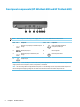
Front panel components (HP EliteDesk 800 and HP ProDesk 600) NOTE: Item Your computer model may look slightly different from the illustration in this section.
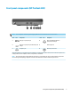
Front panel components (HP ProDesk 400) NOTE: Item Your computer model may look slightly different from the illustration in this section.
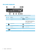
Rear panel components NOTE: Item Your computer model may look slightly different from the illustration in this section. Icon Component Item Icon Component 1 Antenna cover 7 USB SuperSpeed port 2 Thumbscrew 8 Optional port One of the following ports may be used: DisplayPort, HDMI, VGA, USB Type-C, serial port, Thunderbolt, or Fiber NIC.
Serial number location Each computer has a unique serial number and a product ID number that are located on the exterior of the computer. Keep these numbers available for use when contacting support for assistance.
2 Setup Changing from desktop to tower orientation IMPORTANT: Be sure that at least 10.2 centimeters (4 inches) of space on all sides of the computer remains clear and free of obstructions. The computer can be used in a tower orientation with an optional tower stand that can be purchased from HP. NOTE: To stabilize the computer in a tower orientation, HP recommends the use of the optional tower stand. 1. Remove/disengage any security devices that prohibit opening the computer. 2.
IMPORTANT: Be sure that at least 10.2 centimeters (4 inches) of space on all sides of the computer remains clear and free of obstructions. 7. Lock any security devices that were disengaged when the access panel was removed. Attaching the computer to a mounting fixture The computer can be attached to a wall, swing arm, or other mounting fixture. NOTE: This apparatus is intended to be supported by UL or CSA Listed wall-mount bracket. 1.
Installing a security cable The security cable displayed below can be used to secure the computer. NOTE: The security cable is designed to act as a deterrent, but it may not prevent the computer from being mishandled or stolen. Connecting the power cord When connecting the AC adapter, it is important to follow the steps below to ensure that the power cord does not pull free from the computer. 8 1. Connect the power cord to the AC adapter (1). 2. Plug the power cord into an AC outlet (2). 3.
3 Hardware upgrades Serviceability features The computer includes features that make it easy to upgrade and service. No tools are needed for most of the installation procedures described in this chapter. Warnings and cautions Before performing upgrades be sure to carefully read all of the applicable instructions, cautions, and warnings in this guide.
Removing and installing the access panel NOTE: For the HP EliteDesk 800 35W, see Removing and installing the access panel of the HP EliteDesk 800 35W on page 11. Removing the access panel To access internal components, you must remove the access panel: WARNING! To reduce risk of personal injury from hot surfaces, allow the internal system components to cool before you touch them. 1. Remove/disengage any security devices that prohibit opening the computer. 2.
Installing the access panel 1. Place the access panel on the computer and slide it back (1). 2. When the access panel slides into place, tighten the thumbscrew (2) to secure the access panel in place as shown in the following image. NOTE: Your computer model may look slightly different from the illustration in this section. Removing and installing the access panel of the HP EliteDesk 800 35W NOTE: For models other than the HP EliteDesk 800 35W, see Removing and installing the access panel on page 10.
7. Slide the access panel forward, and lift it off the computer (2). WARNING! To reduce risk of personal injury from hot surfaces, allow the internal system components to cool before you touch them. NOTE: Your computer model may look slightly different from the illustrations in this section. 12 8. Disconnect the fan cable (1) from the system board. 9. Remove the three screws (2) securing the DGPU to the system board.
10. Lift the DGPU up by the tab at the fan end and pull the DGPU up out of the chassis. Installing the access panel of the HP EliteDesk 800 35W This procedure includes installing the DGPU and the access panel. 1. Set the DGPU into the chassis and secure it to the system board with three screws: two screws at the fan end of the DGPU and one screw at the inner corner of the opposite end of the DGPU (1). 2. Plug the fan cable into the connector (2) on the system board. 3.
4. When the access panel slides into place, tighten the thumbscrew (2) to secure the access panel in place as shown in the following image. NOTE: Your computer model may look slightly different from the illustration in this section. Upgrading system memory The computer comes with at least one small outline, dual in-line memory module (SODIMM). To achieve maximum memory support, you can populate the system board with up to 32 GB of memory.
Populating memory module slots There are two memory module slots on the system board, with one slot per channel. The sockets are labeled DIMM1 and DIMM3. The DIMM1 slot operates in memory channel B. The DIMM3 slot operates in memory channel A.
Installing a memory module CAUTION: You must disconnect the power cord and wait approximately 30 seconds for the power to drain before adding or removing memory modules. Regardless of the power-on state, voltage is always supplied to the memory modules as long as the computer is plugged into an active AC outlet. Adding or removing memory modules while voltage is present may cause irreparable damage to the memory modules or system board. The memory module slots have gold-plated metal contacts.
6. Tilt the fan up using the front tab and leave it in the up position. NOTE: It is not necessary to fully remove the fan to remove or install a memory module. 7. Locate the memory modules on the system board. 8. To remove a memory module, press outward on the latches (1) on each side of the memory module, and then pull the memory module (2) out of the slot.
9. Slide the new memory module (1) into the slot at approximately a 30° angle, and press the memory module down (2) so that the latches lock it in place. NOTE: A memory module can be installed in only one way. Match the notch on the module with the tab on the memory module slot. 10. Tilt the fan down, and then press the fan down until the it clicks into place. CAUTION: Avoid pulling the fan cable. 11. Install the access panel.
Removing a hard drive NOTE: Before you remove the old hard drive, be sure to back up the data from the old hard drive so that you can transfer the data to the new hard drive. 1. Remove/disengage any security devices that prohibit opening the computer. 2. Remove all removable media, such as a USB flash drive, from the computer. 3. Turn off the computer properly through the operating system, then turn off any external devices. 4.
Installing a hard drive NOTE: Before you remove the old hard drive, be sure to back up the data from the old hard drive so that you can transfer the data to the new hard drive. 20 1. If you are replacing a hard drive, transfer the silver and blue isolation mounting guide screws from the old hard drive to the new hard drive. 2.
5. If the computer was on a stand, replace the stand. 6. Reconnect external devices, plug in the power cord, and then turn on the computer. 7. Lock any security devices that were disengaged when the access panel was removed. Replacing an M.2 PCIe solid-state drive 1. Remove/disengage any security devices that prohibit opening the computer. 2. Remove all removable media, such as a USB flash drive, from the computer. 3.
7. Locate the solid-state drives on the system board. 8. Remove the screw securing a solid-state drive to the system board (1). 9. Grasp the solid-state drive by the sides and carefully pull it out of the socket (2). 10. Remove the screw holder from the solid-state drive (3) for use on the replacement solid-state drive. 11. Insert the screw holder into the niche on the end of the new solid-state drive (1). 12.
13. Press the solid-state drive down to the system board and use the included screw (3) to secure the solidstate drive. 14. If your model is an EliteDesk 800 95W, replace the fan assembly. a. Set the fan assembly in place (1). b. Tighten the three captive screws to secure the fan assembly to the chassis (2). c. Connect the fan assembly plug to the system board (3). 15. Install the access panel.
17. Reconnect external devices, plug in the power cord, and then turn on the computer. 18. Lock any security devices that were disengaged when the access panel was removed. Replacing the WLAN module 1. Remove/disengage any security devices that prohibit opening the computer. 2. Remove all removable media, such as a USB flash drive, from the computer. 3. Turn off the computer properly through the operating system, then turn off any external devices. 4.
7. Locate the WLAN module on the system board. 8. Disconnect both antenna cables (1) from the WLAN module. NOTE: You may need to use a small tool, such as a pair of tweezers or needle-nose pliers, to disconnect and connect the antenna cables. 9. Remove the screw (2) securing the WLAN module to the system board. 10. Grasp the WLAN module (3) by the sides and pull it out of the socket. 11. Insert the new WLAN module into the socket on the system board.
13. Match the label on each antenna cable to the corresponding connector on the WLAN module and attach the antennas (3) to the connectors. 14. If your model is an EliteDesk 800 95W, replace the fan assembly. a. Set the fan assembly in place (1). b. Tighten the three captive screws to secure the fan assembly to the chassis (2). c. Connect the fan assembly plug to the system board (3). 15. Install the access panel.
17. Reconnect external devices, plug in the power cord, and then turn on the computer. 18. Lock any security devices that were disengaged when the access panel was removed. Installing an external antenna Internal WLAN antennas are standard. If the computer is to be installed in a metal kiosk or other enclosure, you may wish or need to use an external WLAN antenna. 1. Remove/disengage any security devices that prohibit opening the computer. 2.
7. Locate the WLAN module on the system board. 8. Disconnect the internal antennas from the WLAN module. For instructions, see Replacing the WLAN module on page 24. 9. Locate both external antenna positions on the rear of the chassis. 10. To view the knock-out feature on the left side of the rear panel, remove the antenna cover by pushing down on the antenna cover (1) and pulling it away (2) from the panel. 11.
13. Connect the external antenna (3) and screw into place (4). 14. If your model is an EliteDesk 800 95W, replace the fan assembly. a. Set the fan assembly in place (1). b. Tighten the three captive screws to secure the fan assembly to the chassis (2). c. Connect the fan assembly plug to the system board (3). 15. Install the access panel. ● For instructions on installing the access panel on a 35W model, see Installing the access panel of the HP EliteDesk 800 35W on page 13.
17. Reconnect external devices, plug in the power cord, and then turn on the computer. 18. Lock any security devices that were disengaged when the access panel was removed. Replacing the battery The battery that comes with the computer provides power to the real-time clock. When replacing the battery, use a battery equivalent to the battery originally installed in the computer. The computer comes with a 3-volt lithium coin cell battery.
7. a. Disconnect the fan assembly plug (1) from the system board. b. Loosen the three captive screws securing the fan assembly (2). c. Lift the fan assembly out of the chassis (3). Locate the battery and battery holder on the system board. NOTE: You may need to use a small tool, such as tweezers or needle-nose pliers, to remove and replace the battery.
8. To release the battery from its holder, squeeze the metal clamp that extends above one edge of the battery (1). When the battery pops up, lift it out (2). 9. To insert the new battery, slide one edge of the replacement battery into the holder with the positive side up (1). Push the other edge down until the clamp snaps over the other edge of the battery (2). 10. If your model is an EliteDesk 800 95W, replace the fan assembly. 32 a. Set the fan assembly in place (1). b.
c. Connect the fan assembly plug to the system board (3). 11. Replace the access panel. ● For instructions on installing the access panel on a 35W model, see Installing the access panel of the HP EliteDesk 800 35W on page 13. ● For instructions on installing the access panel on any other model, see Installing the access panel on page 11. 12. If the computer was on a stand, replace the stand. 13. Reconnect external devices, plug in the power cord, and then turn on the computer. 14.
Synchronizing the optional wireless keyboard and mouse The mouse and keyboard are synchronized at the factory. If they do not work, remove and replace the batteries. If the mouse and keyboard are still not synchronized, then follow this procedure to manually resynchronize the pair. 1. 2. 3.
4. 5. NOTE: If the mouse and keyboard still do not work, then remove and replace the batteries. If the mouse and keyboard are still not synchronized, then synchronize the keyboard and mouse again.
A Electrostatic discharge A discharge of static electricity from a finger or other conductor may damage system boards or other staticsensitive devices. This type of damage may reduce the life expectancy of the device. Preventing electrostatic damage To prevent electrostatic damage, observe the following precautions: ● Avoid hand contact by transporting and storing products in static-safe containers. ● Keep electrostatic-sensitive parts in their containers until they arrive at static-free workstations.
B Computer operating guidelines, routine care and shipping preparation Computer operating guidelines and routine care Follow these guidelines to properly set up and care for the computer and monitor: ● Keep the computer away from excessive moisture, direct sunlight, and extremes of heat and cold. ● Operate the computer on a sturdy, level surface. Leave a 10.2 cm (4 inch) clearance on all vented sides of the computer and above the monitor to permit the required airflow.
Shipping preparation Follow these suggestions when preparing to ship the computer: 1. Back up the SSD files to an external storage device. Be sure that the backup media is not exposed to electrical or magnetic impulses while stored or in transit. 2. Remove and store all removable media. 3. Turn off the computer and external devices. 4. Disconnect the power cord from the AC outlet, then from the computer. 5.
C Accessibility HP designs, produces, and markets products and services that can be used by everyone, including people with disabilities, either on a stand-alone basis or with appropriate assistive devices. Supported assistive technologies HP products support a wide variety of operating system assistive technologies and can be configured to work with additional assistive technologies. Use the Search feature on your device to locate more information about assistive features.
Index A access panel installing 11 removal 10 accessibility 39 antenna connector, external 4 antenna cover 4 audio-out (headphone)/audio-in (microphone) combo jack 2, 3 ProDesk 400 ProDesk 600 H hard drive installation 19, 20 removal 19, 20 headphone jack 2, 3 B battery removal 30 replacement 30 battery replacement 30 buttons power 2, 3 C computer operating guidelines connectors external antenna 4 power 4 D DisplayPort 4 Dual-Mode DisplayPort 37 4 E electrostatic discharge, preventing damage 36 exter
removing access panel 10 battery 30 hard drive 19, 20 memory modules 16 solid-state drive 21 WLAN module 24 RJ-45 (network) jack 4 S security cable installation 8 security cable slot 4 serial number location 5 shipping preparation 38 slots security cable 4 solid-state drive removal 21 replacement 21 specifications, memory modules 14 status lights RJ-45 (network) 4 synchronizing wireless keyboard and mouse 34 T thumbscrew 4 tower conversion 6 U USB ports 4 USB SuperSpeed port 2, 4 USB SuperSpeed port with