Maintenance and Service Guide HP EliteDesk 405 G4 Desktop Mini
© Copyright 2019 HP Development Company, L.P. AMD and Ryzen are trademarks of Advanced Micro Devices, Inc. Bluetooth is a trademark owned by its proprietor and used by HP Inc. under license. DisplayPort is a trademark owned by the Video Electronics Standards Association (VESA) in the United States and other countries. Intel is a trademark of Intel Corporation or its subsidiaries in the U.S. and/or other countries. Microsoft and Windows are trademarks of the Microsoft group of companies.
Safety warning notice WARNING! To reduce the possibility of heat-related injuries or of overheating the device, do not place the device directly on your lap or obstruct the device air vents. Use the device only on a hard, flat surface. Do not allow another hard surface, such as an adjoining optional printer, or a soft surface, such as pillows or rugs or clothing, to block airflow. Also, do not allow the AC adapter to contact the skin or a soft surface, such as pillows or rugs or clothing, during operation.
iv Safety warning notice
Table of contents 1 Product features ........................................................................................................................................... 1 Standard configuration features ........................................................................................................................... 1 Front panel components ........................................................................................................................................
4 Removal and replacement procedures ........................................................................................................... 15 Warnings and cautions ........................................................................................................................................ 15 Preparation for disassembly ............................................................................................................................... 16 Front bezel dust filter ...................
Solving USB flash drive problems ........................................................................................................................ 68 Solving Internet access problems ....................................................................................................................... 68 Solving software problems .................................................................................................................................. 69 6 Computer Setup (F10) Utility ........
10 Power cord set requirements ...................................................................................................................... 99 General requirements .......................................................................................................................................... 99 Japanese power cord requirements .................................................................................................................... 99 Country-specific requirements .............
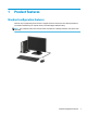
1 Product features Standard configuration features Features may vary depending on the model. For support assistance and to learn more about the hardware and software installed on your computer model, run the HP Support Assistant utility. NOTE: This computer model can be used in a tower orientation or a desktop orientation. The stand is sold separately.
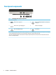
Front panel components Table 1-1 Identifying the front panel components Front panel components 1 USB 3.1 Gen 1 Type A port 4 Audio-out (headphone)/Audio-in (microphone) combo jack 2 USB 3.1 Gen 1 Type A charging port 5 Hard drive activity light 3 Audio-out (headphone) jack 6 Power button NOTE: The USB SuperSpeed port with HP Sleep and Charge provides current to charge a device such as a smart phone.
Rear panel components Table 1-2 Identifying the rear panel components Rear panel components 1 Antenna cover 6 USB SuperSpeed ports (2) 2 External antenna locations 7 Configurable option card slot (DisplayPort™ 1.2, HDMI, VGA, USB Type-C, or serial port) 3 Access panel thumbscrew 8 USB 3.
2 Illustrated parts catalog NOTE: HP continually improves and changes product parts. For complete and current information on supported parts for your computer, go to http://partsurfer.hp.com, select your country or region, and then follow the on-screen instructions.
Table 2-1 Identifying computer major components (continued) Item Description DisplayPort option board VGA option board Serial port option board USB Type-C option board (6) Solid-state drives (NVMe, M.2 2280, PCIe): 512 GB, self-encrypting drive, TLC 512 GB, TLC 512 GB 256 GB, TLC 256 GB, self-encrypting drive, TLC 256 GB 128 GB, TLC (7) Memory module (SODIMM, PC4-2666): 16 GB 8 GB 4 GB (8) Hard drives: 1 TB, 7200 rpm, 9.5 mm 500 GB, 7200 rpm, 7 mm Solid-state drives (2.
Table 2-1 Identifying computer major components (continued) Item Description (16) System board (includes replacement thermal material) (17) Antenna cables, wireless (18) Stand Miscellaneous parts Table 2-2 Identifying miscellaneous parts Description AC adapter (Smart, 65 W, nPFC, 7.
Table 2-2 Identifying miscellaneous parts (continued) Description USB, essential USB Conferencing USB slim USB slim, smart card Antimicrobial finish USB collaboration Wireless collaboration Mouse: USB, optical USB, laser USB/PS2 washable USB antimicrobial finish USB hardened Miscellaneous parts 7
3 Routine care, SATA drive guidelines, and disassembly preparation This chapter provides general service information for the computer. Adherence to the procedures and precautions described in this chapter is essential for proper service. NOTICE: When the computer is plugged into an AC power source, voltage is always applied to the system board. You must disconnect the power cord from the power source before opening the computer to prevent system board or component damage.
Table 3-1 Static electricity occurrence based on activity and humidity (continued) Relative humidity Removing DIPs from vinyl tray 2,000 V 4,000 V 11,500 V Removing DIPs from Styrofoam 3,500 V 5,000 V 14,500 V Removing bubble pack from PCB (printed circuit board) 7,000 V 20,000 V 26,500 V Packing PCBs in foam-lined box 5,000 V 11,000 V 21,000 V Multiple electric components can be packaged together in plastic tubes, trays, or Styrofoam. NOTE: As little as 700 V can degrade a product.
Grounding the work area To prevent static damage at the work area, use the following precautions: ● Cover the work surface with approved static-dissipative material. Provide a wrist strap connected to the work surface and properly grounded tools and equipment. ● Use static-dissipative mats, foot straps, or air ionizers to give added protection. ● Handle electrostatic sensitive components, parts, and assemblies by the case or PCB laminate. Handle them only at static-free work areas.
● Never restrict the airflow into the computer by blocking any vents or air intakes. Do not place the keyboard, with the keyboard feet down, directly against the front of the desktop unit as this also restricts airflow. ● Occasionally clean the air vents on all vented sides of the computer. Lint, dust, and other foreign matter can block the vents and limit the airflow. Be sure to unplug the computer before cleaning the air vents. ● Never operate the computer with the cover or side panel removed.
To clean the tops of the keys or the keyboard body, follow the procedures described in Cleaning the computer case on page 11. When cleaning debris from under the keys, review all rules in General cleaning safety precautions on page 11 before following these procedures: CAUTION: keys. Use safety glasses equipped with side shields before attempting to clean debris from under the ● Visible debris underneath or between the keys may be removed by vacuuming or shaking.
Screws The screws used in the computer are not interchangeable. They could have standard or metric threads and may be of different lengths. If an incorrect screw is used during the reassembly process, it can damage the unit. HP strongly recommends that all screws removed during disassembly be kept with the part that was removed and then returned to their proper locations. CAUTION: As you remove each subassembly from the computer, place it away from the work area to prevent damage.
SATA hard drives Table 3-3 SATA hard drive characteristics Serial ATA hard drive characteristics Number of pins/conductors in data cable 7/7 Number of pins in power cable 15 Maximum data cable length 100 cm (39.37 in) Data interface voltage differential 400 mV-700 mV Drive voltages 3.3 V, 5 V, 12 V Jumpers for configuring drive N/A Data transfer rate 6.
4 Removal and replacement procedures Adherence to the procedures and precautions described in this chapter is essential for proper service. After completing all necessary removal and replacement procedures, run the Diagnostics utility to verify that all components operate properly. NOTE: Not all features listed in this guide are available on all computers. NOTE: HP continually improves and changes product parts.
Preparation for disassembly See Routine care, SATA drive guidelines, and disassembly preparation on page 8 for initial safety procedures. 1. Remove/disengage any security devices that prohibit opening the computer. 2. Remove all removable media, such as a USB flash drive, from the computer. 3. Turn off the computer properly through the operating system, then turn off any external devices. 4. Disconnect the power cord from the AC outlet and disconnect any external devices.
Access panel To access internal components, you must remove the access panel: 1. Prepare the computer for disassembly (Preparation for disassembly on page 16). 2. Remove the thumbscrew on the rear of the computer (1). Then slide the panel forward (2), and then lift it off the computer (3). NOTE: If necessary, a Torx T15 or flat-bladed screwdriver can be used to loosen the thumbscrew. NOTE: Your computer model may look slightly different from the illustration in this section.
Front bezel NOTE: It is not necessary to remove the front bezel to access other components. The front bezel is secured to the top cover by tabs. 1. Prepare the computer for disassembly (Preparation for disassembly on page 16). 2. Remove the access panel (Access panel on page 17). 3. Position the top cover upside-down so you can access the inside of the bezel. 4. Remove the two Phillips screws (1) that secure the bezel to the access panel. 5.
Ambient thermal sensor The ambient thermal sensor is located near the front of the computer. 1. Prepare the computer for disassembly (Preparation for disassembly on page 16). 2. Remove the access panel (Access panel on page 17). 3. Lift the rubber cover from the sensor (1). 4. Disconnect the cable from the system board, and then lift the sensor out of the computer (2). To install the ambient thermal sensor, reverse the removal procedure.
Speaker A single speaker is located on the left side of the computer behind the front bezel, inside the chassis. It is secured by a white peg that you pull out to release. To remove the speaker: 1. Prepare the computer for disassembly (Preparation for disassembly on page 16). 2. Remove the access panel (Access panel on page 17). 3. Disconnect the speaker cable from the system board connector (1). 4. From the front of the computer, remove the Phillips screw that secures the speaker to the chassis (2).
Hard drive Models with a hard drive and drive cage do not include a separate graphics processor card. For a list of available hard drives, see Computer major components on page 4. NOTE: Before you remove the old hard drive, be sure to back up the data from the old hard drive so that you can transfer the data to the new hard drive. 1. Prepare the computer for disassembly (Preparation for disassembly on page 16). 2. Remove the access panel (Access panel on page 17). 3.
Hard drive connector The hard drive connector is installed in the hard drive cage and connects to the system board. 1. Prepare the computer for disassembly (Preparation for disassembly on page 16). 2. Remove the access panel (Access panel on page 17). 3. Remove the hard drive (Hard drive on page 21). 4. Disconnect the cable from the system board (1). 5. Remove the two Torx T15 screws that secure the connector to the drive cage (2). 6. Lift the hard drive connector out of the computer (3).
Drive cage 1. Prepare the computer for disassembly (Preparation for disassembly on page 16). 2. Remove the access panel (Access panel on page 17). 3. Remove the hard drive (Hard drive on page 21). 4. Lift the connector latch on the system board (1), and then disconnect the hard drive cable using the pull tab on the cable (2). 5. Remove the two Torx T15 screws (3) that secure the hard drive cage to the chassis. 6. Slide the hard drive cage back, and then lift it out of the chassis (4).
M.2 PCIe solid state drive (SSD) For a list of available solid-state drives, see Computer major components on page 4. 24 1. Prepare the computer for disassembly (Preparation for disassembly on page 16). 2. Remove the access panel (Access panel on page 17). 3. In models with a hard drive, remove the hard drive (Hard drive on page 21) and drive cage Drive cage on page 23. 4. Locate the M.2 SSD on the system board. 5.
To replace the solid-state drive module, reverse the removal procedures. M.
WLAN module For a list of available WLAN modules, see Computer major components on page 4. 26 1. Prepare the computer for disassembly (Preparation for disassembly on page 16). 2. Remove the access panel (Access panel on page 17). 3. In models with a hard drive, remove the hard drive (Hard drive on page 21) and drive cage Drive cage on page 23. 4. Locate the WLAN module on the system board. 5. Disconnect both antenna cables (1) from the WLAN module.
6. Remove the screw (2) that secures the WLAN module to the system board, and then grasp the WLAN module by the sides and pull it out of the socket (3). NOTE: You may need to use a small tool, such as a pair of tweezers or needle-nose pliers, to disconnect and connect the antenna cables. IMPORTANT: Only disconnect the antenna cables from the WLAN module when necessary, such as when specifically replacing the WLAN module or the antenna cables.
Battery The battery that comes with the computer provides power to the real-time clock. When replacing the battery, use a battery equivalent to the battery originally installed in the computer. The computer comes with a 3-volt lithium coin cell battery. WARNING! The computer contains an internal lithium manganese dioxide battery. There is a risk of fire and burns if the battery is not handled properly. To reduce the risk of personal injury: Do not attempt to recharge the battery.
5. Lift the battery out of the holder. 6. Slide the replacement battery into position, positive side up. The battery holder automatically secures the battery in the proper position. 7. Reassemble the computer. 8. Reset the date and time, your passwords, and any special system setups using Computer Setup.
Expansion connector board For a list of available expansion connector boards, see Computer major components on page 4. An expansion board can be installed near the back of the system board that provides an additional connector on the rear I/O panel. The board is secured with two screws and connects to the a connector on the system board. To remove the expansion connector board: 1. Prepare the computer for disassembly (Preparation for disassembly on page 16). 2.
Memory modules The computer comes with at least one small outline, dual in-line memory module (SODIMM). To achieve maximum memory support, you can populate the system board with up to 32 GB of memory. Memory module specifications For proper system operation, the memory modules must meet the following qualifications: Table 4-1 Memory module specifications Component Specification Memory modules 1.
Table 4-2 Identifying memory module slot system board locations Item Description System board label Slot color 1 Memory module slot, Channel A DIMM3 Black 2 Memory module slot, Channel B DIMM1 Black The system will automatically operate in single channel mode, dual channel mode, or flex mode, depending on how the memory modules are installed. 32 ● The system will operate in single channel mode if the memory module slots are populated in one channel only.
IMPORTANT: You must disconnect the power cord and wait approximately 30 seconds for the power to drain before adding or removing memory modules. Regardless of the power-on state, voltage is always supplied to the memory modules as long as the computer is plugged into an active AC outlet. Adding or removing memory modules while voltage is present may cause irreparable damage to the memory modules or system board. The memory module slots have gold-plated metal contacts.
4. Locate the memory module locations (1) and (2) on the system board. 5. To remove a memory module, press outward on the two latches on each side of the memory module (1), and then pull the memory module (2) out of the slot. The computer automatically recognizes the new memory when you turn on the computer.
Fan 1. Prepare the computer for disassembly (Preparation for disassembly on page 16). 2. Remove the access panel (Access panel on page 17). 3. Disconnect the fan cable from the system board (1). 4. Remove the fan cable from the clips on the side of the heat sink (2). 5. Lift fan up to about 30-45 degrees (3), and then pull it away from the heat sink (4). To install the fan, reverse the removal procedure.
Heat sink IMPORTANT: The bond between the heat sink and the processor may be very tight. If the computer will turn on, before removing the heat sink, turn on the computer until it warms the heat sink. Warming the fan sink lessens the bond between the heat sink and the processor, thereby making separating them easier. Make sure not to pull the processor out of the socket when you lift the heat sink, especially if you cannot warm the fan sink prior to removal.
Heat sink 37
Processor For a list of available processors, see Computer major components on page 4. 1. Prepare the computer for disassembly (Preparation for disassembly on page 16). 2. Remove the access panel (Access panel on page 17). 3. Remove the fan (Fan on page 35). 4. Remove the heat sink (Heat sink on page 36). 5. Unlatch the locking lever from the side of the processor socket (1). 6. Rotate the locking lever to its fully open position (2). 7. Lift the processor straight up to remove it (3).
System board NOTE: All system board spare part kits include replacement thermal material. NOTE: System board appearance may vary. 1. Prepare the computer for disassembly (Preparation for disassembly on page 16). 2. Remove the access panel (Access panel on page 17). 3. In models with a hard drive, remove the hard drive (Hard drive on page 21) and drive cage Drive cage on page 23. 4. Remove the fan (Fan on page 35). 5. Remove the heat sink (Heat sink on page 36). 6.
b. 8. On models without a hard drive, disconnect the speaker cable from the system board (1), and then remove the five Torx T15 screws (2) that secure the system board to the computer. Lift the front of the system board (1), and then pull it out of the computer (2). To install the system board, reverse the removal procedures.
NOTE: When replacing the system board, you must change the chassis serial number in the BIOS. Updating SMBIOS Information When replacing the system board, you must reprogram the SMBIOS information on the affected computer. Failure to reprogram the board will result in eventual failure, such as an activation failure (need to reactivate the system) or a system recovery failure. To update SMBIOS information in Computer Setup: 1. Turn on or restart the computer. 2.
Table 4-3 Identifying system ID setup page fields (continued) Setup Field Name Comment Label Feature Byte Enter the Feature Byte string. The feature byte string is case sensitive. Flexbuild The label includes spaces after every four characters. You can enter or ignore these spaces – their only purpose is to help with data entry. There is a character limitation of 40 bytes per line. When you reach this limit, go to the next line to continue data entry. BIOS ignores the spaces and lines.
Internal WLAN antenna cables The antennas route from the WLAN module to the cable connectors on the front and the rear of the computer. To install the antennas: 1. Prepare the computer for disassembly (Preparation for disassembly on page 16). 2. Remove the access panel (Access panel on page 17). 3. Remove the hard drive (Hard drive on page 21). 4. Remove the drive cage (Drive cage on page 23). 5. Remove the fan (Fan on page 35). 6. Remove the heat sink (Heat sink on page 36). 7.
15. Rotate and remove the antenna (3), and then pull the cable out of the front of the chassis (4). Reverse the removal procedure to install the WLAN antennas and cables.
Changing from desktop to tower configuration The computer can be used in a tower orientation with an optional tower stand that can be purchased from HP. 1. Prepare the computer for disassembly (Preparation for disassembly on page 16). 2. Orient the computer so that its right side is facing up and place the computer in the optional stand. NOTE: To stabilize the computer in a tower orientation, HP recommends the use of the optional tower stand. 3.
5 Troubleshooting without diagnostics This chapter provides information on how to identify and correct minor problems, such as USB devices, hard drive, optical drive, graphics, audio, memory, and software problems. If you encounter problems with the computer, see the tables in this chapter for probable causes and recommended solutions.
If it becomes necessary to call for technical assistance, be prepared to do the following to ensure that your service call is handled properly: ● Be in front of your computer when you call. ● Write down the computer serial number, product ID number, and monitor serial number before calling. ● Spend time troubleshooting the problem with the service technician. ● Remove any hardware that was recently added to your system. ● Remove any software that was recently installed.
● If you have installed an operating system other than the factory-installed operating system, check to be sure that it is supported on the system. ● If the system has multiple video sources (embedded, PCI, or PCI-Express adapters) installed (embedded video on some models only) and a single monitor, the monitor must be plugged into the monitor connector on the source selected as the primary VGA adapter.
Computer date and time display is incorrect. Cause Solution RTC (real-time clock) battery may need to be replaced. Reset the date and time under Control Panel (Computer Setup can also be used to update the RTC date and time). If the problem persists, replace the RTC battery. See the Removal and Replacement section for instructions on installing a new battery, or contact an authorized dealer or reseller for RTC battery replacement.
Poor performance. Cause Solution Hard drive fragmented. Defragment hard drive. Program previously accessed did not release reserved memory back to the system. Restart the computer. Virus resident on the hard drive. Run virus protection program. Too many applications running. 1. Close unnecessary applications to free up memory. 2. Add more memory. 3. Some applications run in the background and can be closed by right-clicking on their corresponding icons in the task tray.
System does not power on and the LEDs on the front of the computer are not flashing. Cause Solution 1. If equipped with a voltage selector, check that the voltage selector (located on the rear of the power supply) is set to the appropriate voltage. Proper voltage setting depends on your region. 2. Remove the expansion cards one at a time until the 5V_aux light on the system board turns on. 3. Replace the system board. OR Press and hold the power button for less than 4 seconds.
Computer powered off automatically and the Power LED flashes Red two times, once every second, followed by a two second pause, and the computer beeps two times. (Beeps stop after fifth iteration but LEDs continue flashing.) Cause Solution 3. If fan a plugged in and not spinning, replace it. Solving hard drive problems Hard drive error occurs. Cause Solution Hard disk has bad sectors or has failed. 1.
Nonsystem disk/NTLDR missing message. Cause Solution The system is trying to start from the hard drive but the hard drive may have been damaged. ▲ Perform Drive Protection System (DPS) testing in system ROM. System files missing or not properly installed. 1. Insert bootable media and restart the computer. 2. Boot to the windows installation media and select the recovery option. If only a restore kit is available, then select the File Backup Program option, and then restore the system. 3.
Solving media card reader problems Media card will not work in a digital camera after formatting it in Windows. Cause Solution By default, Windows will format any media card with a capacity greater than 32MB with the FAT32 format. Some digital cameras use the FAT (FAT16 & FAT12) format and can not operate with a FAT32 formatted card. Either format the media card in the digital camera or select FAT file system to format the media card in a computer with Windows.
After installing the media card reader and booting to Windows, the reader and the inserted cards are not recognized by the computer. Cause Solution The operating system needs time to recognize the device if the reader was just installed into the computer and you are turning the PC on for the first time. Wait a few seconds so that the operating system can recognize the reader and the available ports, and then recognize the media inserted in the reader.
Blank screen (no video). Cause Solution 2. Monitor is configured to use an input that is not active. Expand the Resolution box, and then use the sliding control to reset the resolution. Use the monitor's on-screen menu controls to select the input that is being driven by the system. See the monitor's user documentation for more information on the on-screen controls and settings.
Dim characters. Cause Solution The brightness and contrast controls are not set properly. Adjust the monitor brightness and contrast controls. Cables are not properly connected. Check that the graphics cable is securely connected to the graphics card (if applicable) or video connector and the monitor. Blurry video or requested resolution cannot be set. Cause Solution If the graphics controller was upgraded, the correct graphics drivers may not be loaded.
“Out of Range” displays on screen. Cause Solution Video resolution and refresh rate are set higher than what the monitor supports. Restart the computer and enter Safe Mode. Change the settings to a supported setting then restart the computer so that the new settings take effect. To enter Safe Mode in Windows 10: 1. Log into the computer using an Administrator account. 2. Type msconfig in the taskbar search box, and then select msconfig from the list of applications. 3.
Solving audio problems If the computer has audio features and you encounter audio problems, see the common causes and solutions listed in the following table. Sound cuts in and out. Cause Solution Processor resources are being used by other open applications. Shut down all open processor-intensive applications. Sound does not come out of the speaker or headphones. Cause Solution Software volume control is turned down or muted.
Sound from headphones is not clear or muffled. Cause Solution Headphones are plugged into the rear audio output connector. The rear audio output connector is for powered audio devices and is not designed for headphone use. Plug the headphones into the headphone connector on the front of the computer. Computer appears to be locked up while recording audio. Cause Solution The hard disk may be full. Before recording, make sure there is enough free space on the hard disk.
Printer will not print. Cause Solution where [printer port] is the address of the printer being used. If the printer works, reload the printer driver. To run MS-DOS commands, press the Windows key + r, type cmd in the Open box, and then click OK. If you are on a network, you may not have made the connection to the printer. Make the proper network connections to the printer. Printer may have failed. Run printer self-test. Printer will not turn on.
Keyboard commands and typing are not recognized by the computer. Cause Solution Keyboard connector is not properly connected. Shut down the computer, reconnect the keyboard to the back of the computer, and then restart the computer. Program in use has stopped responding to commands. Shut down your computer using the mouse and then restart the computer. Keyboard needs repairs. See the Worldwide Limited Warranty for terms and conditions. Computer is in Sleep state.
Solving hardware installation problems You may need to reconfigure the computer when you add or remove hardware, such as an additional drive or expansion card. If you install a plug and play device, Windows automatically recognizes the device and configures the computer. If you install a non-plug and play device, you must reconfigure the computer after completing installation of the new hardware. In Windows, use the Add Hardware Wizard and follow the instructions that appear on the screen.
Power LED flashes Red three times and then white two times. Cause Solution Memory is installed incorrectly or is bad. CAUTION: To avoid damage to the DIMMs or the system board, you must unplug the computer power cord before attempting to reseat, install, or remove a DIMM module. 1. Reseat DIMMs. Power on the system. 2. Replace DIMMs one at a time to isolate the faulty module. NOTE: DIMM1 or XMM1 must always be installed.
Network status link light never flashes. NOTE: The network status light is supposed to flash when there is network activity. Cause Solution To access Device Manager in Windows 10, type device manager in the taskbar search box, and then select Device Manager from the list of applications. Network driver is not properly loaded. Reinstall network drivers. System cannot autosense the network. Disable auto-sensing capabilities and force the system into the correct operating mode.
Network controller stops working without apparent cause. Cause Solution The cable is not securely connected. Ensure that the cable is securely attached to the network connector and that the other end of the cable is securely attached to the correct device. The network controller is defective. Contact an authorized service provider. New network card will not boot. Cause Solution New network card may be defective or may not meet industrystandard specifications.
System will not boot or does not function properly after installing additional memory modules. Cause Solution A memory module is not installed in the DIMM1 or XMM1 socket. Ensure that a memory module is installed in the DIMM1 or XMM1 socket on the system board. This socket must be populated with a memory module. Memory module is not the correct type or speed grade for the system or the new memory module is not seated properly. Replace module with the correct industry-standard device for the computer.
Solving USB flash drive problems If you encounter USB flash drive problems, common causes and solutions are listed in the following table. USB flash drive is not seen as a drive letter in Windows. Cause Solution The drive letter after the last physical drive is not available. Change the default drive letter for the flash drive in Windows. USB flash drive not found (identified). Cause Solution The device is attached to a USB port that has been hidden in Computer Setup.
Unable to connect to the Internet. Cause Solution Cable/DSL service is not available or has been interrupted due to bad weather. Try connecting to the Internet at a later time or contact your ISP. (If the cable/DSL service is connected, the “cable” LED light on the front of the cable/DSL modem will be on.) The CAT5 UTP cable is disconnected. Connect the CAT5 UTP cable between the cable modem and the computerss RJ-45 connector.
“Illegal Operation has Occurred” error message is displayed. 70 Cause Solution Software being used is not Microsoft-certified for your version of Windows. Verify that the software is certified by Microsoft for your version of Windows (see program packaging for this information). Configuration files are corrupt. If possible, save all data, close all programs, and restart the computer.
6 Computer Setup (F10) Utility Computer Setup (F10) Utilities Use Computer Setup (F10) Utility to do the following: ● Change settings from the defaults or restore the settings to default values. ● View the system configuration, including settings for processor, graphics, memory, audio, storage, communications, and input devices. ● Modify the boot order of bootable devices such as hard drives, optical drives, or USB flash media devices.
4. Use the arrow (left and right) keys to select the appropriate heading. Use the arrow (up and down) keys to select the option you want, then press Enter. To return to the Computer Setup Utilities menu, press Esc. 5. To apply and save changes, select Main > Save Changes and Exit. ● If you have made changes that you do not want applied, select Ignore Changes and Exit. ● To restore settings from the Advanced and Main menus to original values, select Apply Factory Defaults and Exit.
Computer Setup–Main NOTE: Support for specific Computer Setup options may vary depending on the hardware configuration. Table 6-1 Computer Setup—Main Option Description System Information Lists all information in following list if Advanced System Information is selected. Lists smaller subset if Basic System Information is selected.
Table 6-1 Computer Setup—Main (continued) Option Update System BIOS Description ● Provide detailed system information ● Hardware subsystem tests ● Component tests ● Show test logs ● Language selection Lets you update the system BIOS from www.hp.com or another network server, from a removable USB drive, or from a file located on the hard drive. Displays current BIOS version information. ● Check HP.
Table 6-1 Computer Setup—Main (continued) Option Description Apply Custom Defaults and Exit Applies the custom default settings to the computer after rebooting. Does not apply to options in the Security menu. Apply Factory Defaults and Exit Restores the factory system configuration settings to the computer after rebooting. Does not apply to options in the Security menu. Ignore Changes and Exit Exits Computer Setup without applying or saving any changes.
Table 6-2 Computer Setup—Security (continued) Option Description ● Requires at least one lower case character ● Allow spaces Clear Password Jumper Select Honor to allow or Ignore to not allow the absence of the password jumper to clear the passwords at boot up. Default is Honor. Security Configuration TPM Embedded Security ● TPM Specification Version Displays the current TPM version. ● TPM Device Lets you set the Trusted Platform Module as available or hidden.
Table 6-2 Computer Setup—Security (continued) Option Description ● Unprovision SPM Physical Presence Interface. Notifies the user upon system power up when changes are made to system security policy. The user must agree to the changes to confirm them. Default is enabled. Smart Cover ● Cover Lock. Default is Unlock. ● Cover Removal Sensor. Lets you disable the cover sensor or configure what action is taken if the computer cover was removed. Default is Disabled.
Table 6-2 Computer Setup—Security (continued) Option Description Recover in the event of corruption - automatically recover with no prompting. System Management Command Allows authorized personnel to reset security settings during a service event. Default is enabled. Restore Security Settings to Default This action resets security devices, clears BIOS passwords (not including DriveLock), and restores settings in the Security menu to factory defaults.
Table 6-3 Computer Setup—Advanced (for advanced users) (continued) Option Heading Recovery from Network Allows network recovery as the primary source. Recover after Boot Failure Allows the system to initiate recovery after failing to find a valid boot source. Secure Boot Configuration Configure Legacy Support and Secure Boot Lets you turn off all legacy support on the computer, including booting to DOS, running legacy graphics cards, booting to legacy devices, and so on.
Table 6-3 Computer Setup—Advanced (for advanced users) (continued) Option Heading PCI Express Slot x (enable/disable) Lets you disable individual expansion slots. Default is enabled. M.2 SSD Lets you disable the M.2 solid-state drive slot. Default is enabled. Allow PCIe/PCI SERR# Interrupt (enable/disable) Allows PCI devices to report PCI/PCIe System Error signals, such as address parity errors, data parity errors, and critical errors other than parity. Default is enabled.
Table 6-3 Computer Setup—Advanced (for advanced users) (continued) Option Heading Select to enable control of WLAN function based on wired network connection status. Wake on WLAN Select to enable the WLAN device to wake the system from suspend states. Port Options Lets you disable the following ports (default is enabled): Serial Port A (rear port optional component) SATA 0 Front USB ports - front USB port 1 is the USB Type-C port.
Table 6-3 Computer Setup—Advanced (for advanced users) (continued) Option Heading S3 (Stand By)= 3 blinks at 1Hz (50% duty cycle) followed by a pause of 2 seconds (white LED) — repeated cycles of 3 blinks and a pause. S4 (Hibernation)= 4 blinks at 1Hz (50% duty cycle) followed by a pause of 2 seconds (white LED) — repeated cycles of 4 blinks and a pause. S5 (Soft Off) = LED is off.
7 POST error messages and diagnostic front panel LEDs and audible codes This appendix lists the error codes, error messages, and the various indicator light and audible sequences that you may encounter during Power-On Self-Test (POST) or computer restart, the probable source of the problem, and steps you can take to resolve the error condition. POST Message Disabled suppresses most system messages during POST, such as memory count and nonerror text messages.
Control panel message 008–Microcode Patch Error 009–PMM Allocation Error during MEBx Download Recommended action RTC (real-time clock) battery may need to be replaced. problem persists, replace the RTC battery. See the Removal and Replacement section for instructions on installing a new battery. Processor is not supported by the BIOS. 1. Upgrade BIOS to proper version. 2. Change the processor. 1. Reboot the computer. 2.
Control panel message Description Recommended action 00E-Inventory Error during MEBx Execution BIOS information passed to the MEBx resulted in a failure. 1. Reboot the computer. 2. If the error persists, update to the latest BIOS version. 3. If the error still persists, replace the system board. 1. Reboot the computer. 2. If the error persists, update to the latest BIOS version. 3. If the error still persists, replace the system board.
Control panel message 302-Hard Disk 2: SMART Hard Drive Detects Imminent Failure 309 – 30C: Hard Disk 3–6: SMART Hard Drive Detects Imminent Failure Hard drive is about to fail. (Some hard drives have a hard drive firmware patch that will fix an erroneous error message.) Hard drive is about to fail. (Some hard drives have a hard drive firmware patch that will fix an erroneous error message.) Recommended action 3. Back up contents and replace hard drive. 1.
Control panel message Description Recommended action 3. Reconfigure card resources and/or run Computer Setup or Windows utilities. If a PCI expansion card was recently added, remove it to see if the problem remains. 419-Out of Memory Space for Option ROMs Recently added PCI expansion card contains an option ROM too large to download during POST. ▲ 41A-Front USB1/USB2 Not Connected Front USB cable has been detached or unseated from system board. Reconnect or replace front USB cable.
Control panel message Description Recommended action 90B-Fan Failure The system has detected that a cooling fan is not operating correctly. 1. Reseat fan. 2. Reseat fan cable. 3. Replace fan. 90D-System Temperature Thermal shutdown occurred. The system BIOS has detected your machine was previously shut down to avoid overheating. Overheating may occur if the cooling vents are blocked or the operating temperature exceeds the system specifications.
Table 7-1 Interpreting system validation diagnostic front panel LEDs and audible codes (continued) Number of long beeps/blinks Error category 3 Hardware 4 Thermal 5 System board Patterns of blink/beep codes are determined by using the following parameters: ● 1 second pause occurs after the last major blink. ● 2 second pause occurs after the last minor blink. ● Beep error code sequences occur for the first 5 iterations of the pattern and then stop.
Table 7-2 Interpreting patterns of blink/beep codes (continued) Category Major/minor code 5.5 Description The embedded controller rebooted the system after a possible lockup condition had been detected through the use of a System Health Timer, Automated System Recovery Timer, or other mechanism. * Indicates hardware triggered event; all other events are controlled by the BIOS.
8 Password security and resetting CMOS This computer supports security password features, which can be established through the Computer Setup Utilities menu. This computer supports two security password features that are established through the Computer Setup Utilities menu: administrator password and power-on password. When you establish only an administrator password, any user can access all the information on the computer except Computer Setup.
1. Shut down the operating system properly, then turn off the computer and any external devices, and disconnect the power cord from the power outlet. 2. With the power cord disconnected, press the power button again to drain the system of any residual power. WARNING! To reduce the risk of personal injury from electrical shock and/or hot surfaces, be sure to disconnect the power cord from the wall outlet, and allow the internal system components to cool before touching.
Clearing and resetting the BIOS The CMOS button resets BIOS settings to default, but does not clear the passwords or affect any of the other Security settings. On Intel systems with advanced manageability features, the CMOS button will also partially unprovision AMT. 1. Turn off the computer and any external devices, and disconnect the power cord from the power outlet. 2. Disconnect the keyboard, monitor, and any other external equipment connected to the computer.
9 Using HP PC Hardware Diagnostics Using HP PC Hardware Diagnostics Windows (select products only) HP PC Hardware Diagnostics Windows is a Windows-based utility that allows you to run diagnostic tests to determine whether the computer hardware is functioning properly. The tool runs within the Windows operating system in order to diagnose hardware failures. If HP PC Hardware Diagnostics Windows is not installed on your computer, first you must download and install it.
Downloading the latest HP PC Hardware Diagnostics Windows version To download HP PC Hardware Diagnostics Windows, follow these steps: 1. Go to http://www.hp.com/go/techcenter/pcdiags. The HP PC Diagnostics home page is displayed. 2. Select Download HP Diagnostics Windows, and then select a location on your computer or a USB flash drive. The tool is downloaded to the selected location.
NOTE: To start diagnostics on a convertible computer, your computer must be in notebook mode, and you must use the attached keyboard. NOTE: If you need to stop a diagnostic test, press esc. Starting HP PC Hardware Diagnostics UEFI To start HP PC Hardware Diagnostics UEFI, follow these steps: 1. Turn on or restart the computer, and quickly press esc. 2. Press f2. The BIOS searches three places for the diagnostic tools, in the following order: a.
1. Go to http://www.hp.com/support. 2. Enter the product name or number, select your computer, and then select your operating system. 3. In the Diagnostics section, follow the on-screen instructions to select and download the specific UEFI Diagnostics version for your computer. Using Remote HP PC Hardware Diagnostics UEFI settings (select products only) Remote HP PC Hardware Diagnostics UEFI is a firmware (BIOS) feature that downloads HP PC Hardware Diagnostics UEFI to your computer.
● Set a location for storing the test results. You can also set the user name and password settings used for uploads. ● Display status information about the diagnostics run previously. To customize Remote HP PC Hardware Diagnostics UEFI settings, follow these steps: 1. Turn on or restart the computer, and when the HP logo appears, press f10 to enter Computer Setup. 2. Select Advanced, and then select Settings. 3. Make your customization selections. 4.
10 Power cord set requirements The power supplies on some computers have external power switches. The voltage select switch feature on the computer permits it to operate from any line voltage between 100-120 or 220-240 volts AC. Power supplies on those computers that do not have external power switches are equipped with internal switches that sense the incoming voltage and automatically switch to the proper voltage.
Country-specific requirements Additional requirements specific to a country are shown in parentheses and explained below.
11 Statement of memory volatility The purpose of this chapter is to provide general information regarding nonvolatile memory in HP Business computers. This chapter also provides general instructions for restoring nonvolatile memory that can contain personal data after the system has been powered off and the hard drive has been removed. HP Business computer products that use Intel-based or AMD-based system boards contain volatile DDR memory.
g. If a DriveLock password is set, select the Security menu, and scroll down to Hard Drive Utilities under the Utilities menu. Select Hard Drive Utilities, select DriveLock, then uncheck the checkbox for DriveLock password on restart. Select OK to proceed. h. Select the Main menu, and then select Reset BIOS Security to factory default. Click Yes at the warning message. The computer will reboot. i.
c. Select Hard Drive Utilities. d. Under Utilities, select Disk Sanitizer, select the hard drive storing the data you want to clear, and then follow the on-screen instructions to continue.
Table 11-1 Troubleshooting steps for nonvolatile memory usage (continued) Nonvolatile memory type Amount (Size) Does this memory store customer data? System BIOS 9 MB Yes Does this memory retain data when power is removed? Yes What is the purpose of this memory? Stores system BIOS code and computer configuration data. How is data input into this memory? How is this memory write-protected? System BIOS code is programmed at the factory. Code is updated when the system BIOS is updated.
Table 11-1 Troubleshooting steps for nonvolatile memory usage (continued) Nonvolatile memory type Amount (Size) Does this memory store customer data? Does this memory retain data when power is removed? What is the purpose of this memory? How is data input into this memory? How is this memory write-protected? upgrade is necessary to address a unique issue. Fingerprint reader (select products only) 512 KB flash Yes Yes Stores fingerprint templates.
4. What kind of configuration data is stored on the DIMM Serial Presence Detect (SPD) memory module? How would this data be written? The DIMM SPD memory contains information about the memory module, such as size, serial number, data width, speed/timing, voltage, and thermal information. This information is written by the module manufacturer and stored on an EEPROM. This EEPROM cannot be written to when the memory module is installed in a computer.
12 Specifications Table 12-1 Specifications U.S. Metric Height 6.9 in 175 mm Width 7.0 in 177 mm Depth 1.3 in 34 mm Approximate Weight 3.9 lb 1.77 kg Operating 41° to 113°F 5° to 45°C Nonoperating -40° to 151°F -40° to 66°C Operating 5 - 90% 5 - 90% Nonoperating (38.
Index A access panel illustrated 4 locked 49 removal 17 administrator password 91 ambient thermal sensor removal and replacement 19 audible codes 88 audio problems 59 B battery disposal 13 installation 28 removal 28 battery replacement 28 beep codes 88 BIOS clearing and resetting 93 booting options Full Boot 83 Quick Boot 83 C cable management 14 cable pinouts, SATA data 14 cleaning computer 11 mouse 12 safety precautions 11 CMOS backing up 91 computer specifications 107 computer cleaning 11 Computer Setup
mouse cleaning 12 problems 61 N network problems 64 nonvolatile memory 101 numeric error codes 83 O operating guidelines 10 overheating, prevention 10 P password administrator 91 clearing 91 power-on 91 POST error messages 83 power cord set requirements country specific 100 power problems 51 power supply operating voltage range 107 power-on password 91 printer problems 60 problems audio 59 Computer Setup 48 F10 Setup 48 flash drive 68 general 48 hard drive 52 hardware installation 63 Internet access 68 keyb