HP 7 Plus G2 Tablet Maintenance and Service Guide IMPORTANT! This document is intended for HP authorized service providers only.
© Copyright 2014 Hewlett-Packard Development Company, L.P. Bluetooth is a trademark owned by its proprietor and used by Hewlett-Packard Company under license. SD Logo is a trademark of its proprietor. The information contained herein is subject to change without notice. The only warranties for HP products and services are set forth in the express warranty statements accompanying such products and services. Nothing herein should be construed as constituting an additional warranty.
Safety warning notice WARNING! To reduce the possibility of heat-related injuries or of overheating the device, do not place the device directly on your lap or obstruct the device air vents. Use the device only on a hard, flat surface. Do not allow another hard surface, such as an adjoining optional printer, or a soft surface, such as pillows or rugs or clothing, to block airflow. Also, do not allow the AC adapter to contact the skin or a soft surface, such as pillows or rugs or clothing, during operation.
iv Safety warning notice
Table of contents 1 Product description ........................................................................................................................................... 1 2 External component identification ..................................................................................................................... 2 3 Illustrated parts catalog .....................................................................................................................................
7 Power cord set requirements .......................................................................................................................... 27 Requirements for all countries ............................................................................................................ 27 Requirements for specific countries and regions ............................................................................... 27 8 Recycling ......................................................................
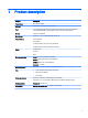
1 Product description Category Description Product Name HP 7 Plus G2 Tablet Processor Intel® Z2520 1.20-GHz dual core processor Panel 7.0-in [1024×600], AG, IPS, LED, multi-touch, wide-viewing angle, 5-point capacitive, auto-rotate [selectable], tempered-glass, backlit, TouchScreen display panel Memory Supports 1.0-GB DDR Mass storage Supports 8.0- or 16.0-GB eMMC solid-state drives Audio and video One microphone One speaker 2.0-MP, fixed-focus, HD, rear-facing webcamera 0.
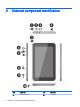
2 2 External component identification Item Component Item Component (1) Rear-facing webcam (6) Power button Chapter 2 External component identification
Item Component Item Component (2) Micro USB 2.
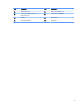
3 Illustrated parts catalog NOTE: HP continually improves and changes product parts. For complete and current information on supported parts for your computer, go to http://partsurfer.hp.com, select your country or region, and then follow the on-screen instructions. Locating the product number and serial number The tablet product number (1) and serial number (2) are located on the tablet back cover. This information may be needed when travelling internationally or when contacting support.
Tablet major components Item Component Spare part number (1) Back cover (includes antenna and power/volume button actuator) 790586-001 (2) Speaker (includes cables) 790591-001 (3) Audio jack light pipe (4) Rear-facing webcam (2.0-MP, fixed-focus, HD; includes cable) 790595-001 (5) Front-facing webcam (0.
Miscellaneous parts Component Spare part number 5-V / 1-A AC adapter: For use in Asia/Pacific countries and regions 791731-004 For use in Europe 791731-009 For use in Latin America 791731-007 For use in North America 791731-008 For use in the United Kingdom 791731-003 Cable Kit 745159-001 HP 7 Plus G2 Tablet equipped with a 7.
Spare part number Description 790595-001 Rear-facing webcam (2.0-MP, fixed-focus, HD; includes cable) 790596-001 Connector board (includes SD Card reader slot, SIM slot, and cable) 790597-001 Microphone (includes cable) 790598-001 Rubber Kit (includes rear-facing webcam rubber lens cover) 790599-001 Plastics Kit 790600-001 Antenna Kit (includes the antenna transceiver, cable, and double-sided adhesive) 790601-001 HP 7 Plus G2 Tablet equipped with a 7.
4 Removal and replacement preliminary requirements Tools required You will need the following tools to complete the removal and replacement procedures: ● Magnetic screw driver ● Phillips P0 screw driver ● Plastic case utility tool Service considerations The following sections include some of the considerations that you must keep in mind during disassembly and assembly procedures.
Grounding guidelines Electrostatic discharge damage Electronic components are sensitive to electrostatic discharge (ESD). Circuitry design and structure determine the degree of sensitivity. Networks built into many integrated circuits provide some protection, but in many cases, ESD contains enough power to alter device parameters or melt silicon junctions. A discharge of static electricity from a finger or other conductor can destroy static-sensitive devices or microcircuitry.
Packaging and transporting guidelines Follow these grounding guidelines when packaging and transporting equipment: ● To avoid hand contact, transport products in static-safe tubes, bags, or boxes. ● Protect ESD-sensitive parts and assemblies with conductive or approved containers or packaging. ● Keep ESD-sensitive parts in their containers until the parts arrive at static-free workstations. ● Place items on a grounded surface before removing items from their containers.
Equipment guidelines Grounding equipment must include either a wrist strap or a foot strap at a grounded workstation. ● When seated, wear a wrist strap connected to a grounded system. Wrist straps are flexible straps with a minimum of one megohm ±10% resistance in the ground cords. To provide proper ground, wear a strap snugly against the skin at all times. On grounded mats with banana-plug connectors, use alligator clips to connect a wrist strap.
5 Removal and replacement procedures NOTE: HP continually improves and changes product parts. For complete and current information on supported parts for your computer, go to http://partsurfer.hp.com, select your country or region, and then follow the on-screen instructions. Tablet component replacement procedures CAUTION: Tablet components described in this chapter should only be accessed by an authorized service provider. Accessing these parts can damage the tablet and void the warranty.
4. Remove the back cover (3). NOTE: If the volume button actuator (1) and power button actuator (2) should become displaced during the removal of the back cover, install the actuator into the openings in the back cover as indicated in the following illustration. The actuators are included in the back cover spare part kit.
Reverse this procedure to install the back cover. Battery Description Spare part number Battery (3100-mAh, USB-charging; includes cable and double-sided adhesive) 790587-001 Before removing the battery, follow these steps: 1. Turn off the tablet. If you are unsure whether the tablet is off or in Hibernation, turn the tablet on, and then shut it down through the operating system. 2. Disconnect the power from the tablet by unplugging the power cord from the tablet. 3.
5. Remove the battery (5). Reverse this procedure to install the battery.
Antenna Description Spare part number Antenna (included in the Antenna Kit, spare part number 790600-001. Includes the antenna transceiver, cable, and doublesided adhesive.) Before removing the antenna, follow these steps: 1. Turn off the tablet. If you are unsure whether the tablet is off or in Hibernation, turn the tablet on, and then shut it down through the operating system. 2. Disconnect the power from the tablet by unplugging the power cord from the tablet. 3.
5. Remove the antenna transceiver (5) and cable. 6. Remove the antenna board and cables. Reverse this procedure to install the antenna board. Speaker Description Spare part number Speaker (includes cables) 790591-001 Before removing the speaker, follow these steps: 1. Turn off the tablet. If you are unsure whether the tablet is off or in Hibernation, turn the tablet on, and then shut it down through the operating system. 2.
1. Unsolder the red and black speaker cables (1) from the system board speaker contact points. NOTE: When installing the speaker, the red speaker cable should be soldered to the system board speaker “positive” terminal. The black speaker cable should be soldered to the system board speaker “negative” terminal. 2. Release the speaker cables from the retention clips (2) built into the speaker. 3. Remove the two Phillips PM1.4×3.6 screws (3) that secure the speaker to the display panel assembly. 4.
Rear-facing webcam Description Spare part number Rear-facing webcam (2.0-MP, fixed-focus, HD; includes cable) 790595-001 Before removing the rear-facing webcam, follow these steps: 1. Turn off the tablet. If you are unsure whether the tablet is off or in Hibernation, turn the tablet on, and then shut it down through the operating system. 2. Disconnect the power from the tablet by unplugging the power cord from the tablet. 3. Disconnect all external devices from the tablet. 4.
Microphone Description Spare part number Microphone (includes cable) 790597-001 Before removing the microphone, follow these steps: 1. Turn off the tablet. If you are unsure whether the tablet is off or in Hibernation, turn the tablet on, and then shut it down through the operating system. 2. Disconnect the power from the tablet by unplugging the power cord from the tablet. 3. Disconnect all external devices from the tablet. 4. Remove the back cover (see Back cover on page 12). 5.
Reverse this procedure to install the microphone. Connector board Description Spare part number Connector board (includes SD Card reader slot, SIM slot, and cable) 790596-001 Before removing the connector board, follow these steps: 1. Turn off the tablet. If you are unsure whether the tablet is off or in Hibernation, turn the tablet on, and then shut it down through the operating system. 2. Disconnect the power from the tablet by unplugging the power cord from the tablet. 3.
5. Remove the Phillips PM1.4×3.6 screw (1) and the Phillips PM1.4×2.2 broad head screw (2) that secure the connector board to the display panel assembly. 6. Remove the connector board (3). Reverse this procedure to install the connector board. System board Description Spare part number System board equipped with an Intel Z2520 1.20-GHz dual core processor, a graphics subsystem with UMA memory, and 1.
5. Disconnect the battery cable from the system board (see Battery on page 14). 6. Remove the speaker (see Speaker on page 17). Remove the system board: [callout 5 IDing button board cable ZIF connector on system board] 1.
5. Remove the system board (4). Reverse this procedure to install the system board. Front-facing webcam Description Spare part number Front-facing webcam (0.3-MP, fixed-focus, VGA; includes cable and double-sided adhesive) 790594-001 Before removing the front-facing webcam, follow these steps: 1. Turn off the tablet. If you are unsure whether the tablet is off or in Hibernation, turn the tablet on, and then shut it down through the operating system. 2.
2. Detach the front-facing webcam (2) from the display panel assembly. (The front-facing webcam is attached to the display panel assembly with double-sided adhesive.) 3. Remove the front-facing webcam and cable. Reverse this procedure to install the front-facing webcam.
6 Specifications Metric U.S. Width 19.3 cm 7.6 in Depth 11.7 cm 4.6 in Height 0.9 cm 0.4 in Weight (lowest weight configuration) 287 g 0.63 lb Dimensions (portrait orientation) Input power The tablet operates on DC power, which can be supplied by an AC or a DC power source. The AC power source must be rated 100-240 V, 50/60 Hz. NOTE: The tablet can operate on DC power using an industry-standard micro-B USB cable. The HP adapter included with the tablet is recommended for charging the tablet.
7 Power cord set requirements The wide-range input feature of the tablet permits it to operate from any line voltage from 100 to 120 volts AC, or from 220 to 240 volts AC. The 3-conductor power cord set included with the tablet meets the requirements for use in the country or region where the equipment is purchased. Power cord sets for use in other countries and regions must meet the requirements of the country or region where the tablet is used.
28 Country/region Accredited agency Applicable note number Sweden CEMKO 1 Switzerland SEV 1 Taiwan BSMI 4 The United Kingdom BSI 1 The United States UL 2 1. The flexible cord must be Type HO5VV-F, 3-conductor, 1.0-mm² conductor size. Power cord set fittings (appliance coupler and wall plug) must bear the certification mark of the agency responsible for evaluation in the country or region where it will be used. 2. The flexible cord must be Type SPT-3 or equivalent, No.
8 Recycling When a non-rechargeable or rechargeable battery has reached the end of its useful life, do not dispose of the battery in general household waste. Follow the local laws and regulations in your area for battery disposal. HP encourages customers to recycle used electronic hardware, HP original print cartridges, and rechargeable batteries. For more information about recycling programs, see the HP Web site at http://www.hp.com/recycle.
Index A AC adapter, spare part numbers 7 antenna removal 16 spare part number 5, 7 Antenna Kit, spare part number 5, 7, 16 audio, product description 1 audio-in jack 3 audio-out jack 3 B back cover removal 12 spare part number battery removal 14 spare part number buttons power 2 volume control 3 H headphone jack 5, 6, 14 J jacks audio-in 3 audio-out 3 headphone 3 microphone 3 D display panel assembly, spare part number 5, 6, 12 display panel, product description 1 E electrostatic discharge 9 equipment g
connectors 8 plastic parts 8 serviceability, product description 1 SIM slot 3 speaker location 3 removal 17 spare part number 5, 6, 17 system board removal 22 spare part numbers 5, 6, 22 T tablet major components 5 spare part numbers 6, 7 specifications 26 tools required 8 transporting guidelines 10 U USB 2.