HP E-MSM720 Controllers Installation Guide Abstract This document describes how to install and initially configure the E-MSM720 Controllers. This document applies to the E-MSM720 Access Controller (J9693A) and the E-MSM720 Premium Mobility Controller (J9694A). These products are hereafter referred to as controller. See also the MSM7xx Controllers Configuration Guide.
© Copyright 2011 Hewlett-Packard Development Company, L.P. The information contained herein is subject to change without notice. The only warranties for HP products and services are set forth in the express warranty statements accompanying such products and services. Nothing herein should be construed as constituting an additional warranty. HP shall not be liable for technical or editorial errors or omissions contained herein. Acknowledgments Microsoft® is a U.S.
Contents 1 Identifying controller physical features...........................................................4 Unpacking the controller............................................................................................................4 Identifying front-panel features....................................................................................................4 Resetting to factory defaults.......................................................................................................
1 Identifying controller physical features Unpacking the controller Unpack your controller and verify that you have received these items: • Controller • External AC/DC power adapter • AC/DC power adapter power cord (for your region) • Console port serial cable (DB-9 to RJ-45) • Documentation including Safety and Regulatory information • Software License, Warranty, and Support information • Accessory kit comprised of: ◦ Two wall-mount brackets ◦ Two 19-inch rack-mount adapter brackets with fo
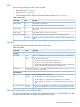
LEDs There are three groupings of LEDs on the controller: • Status LEDs (Table 1 (page 5)) • Port LEDs (Table 2 (page 5)) • Port LED Mode indicator LEDs (near the Mode selector button) (Table 3 (page 6)) Table 1 Status LEDs Status LEDs State Meaning Power (green) On The controller is powered on. Off No power connection. The controller is NOT receiving power. Fault (orange) On The controller is beginning its boot sequence. Turns on for three seconds at power up or reset.
Figure 2 LED mode select button and LEDs 1 2 3 4 1. LED Mode Select button 3. Port Link LED 2. Mode Indicator LEDs (Act, FDx, Spd) 4. Port Mode LED Table 3 Port LED mode indicator LEDs Mode Meaning Act The Port Mode LED displays network activity. FDx The Port Mode LED is on when the port is in full-duplex mode. Spd The Port Mode LED indicates port speed. If the Port Mode LED is off, the port is operating at 10 Mbps. if the Port Mode LED is blinking, the port is operating at 100 Mbps.
2 Installing the controller WARNING! • For indoor use only. The controller, AC power adapter, and all connected cables are not designed for outdoor use. • The HP mini-GBICs are Class 1 laser devices. Avoid direct eye exposure to the beam coming from the transmit port. • The rack or cabinet should be adequately secured to prevent it from becoming unstable and/or falling over.
CAUTION: • Ensure all port covers are installed when the port is not in use. • There are no user-serviceable parts inside these products. Any servicing, adjustment, maintenance, or repair must be performed only by service-trained personnel. • These products do not have a power switch; they are powered on when the power cord is plugged in. Installation procedures These steps summarize your controller installation. The rest of this chapter provides details on these steps.
Figure 3 Connecting the power cord CAUTION: Use only the AC/DC power adapter and power cord supplied with the controller. Use of other adapters or power cords, including those that came with other HP Networking products, may result in damage to the equipment. NOTE: The controller does not have a power switch. It is powered on when the external AC/DC power adapter is connected to the controller and the adapter power cord is connected to a power source.
LED behavior During the self test: • Initially, all the controller and port LEDs are on. Most of the LEDs turn off and then may turn on again during phases of the self test. • For the duration of the self test, the Test LED stays on. When the self test completes successfully: • The Power LED remains on. • The Fault, Locator and Test LEDs stay off. • The Act LED remains on indicating the default port LED mode.
1. Use a #1 Phillips (cross-head) screwdriver and attach the mounting brackets to the controller with the included 8 mm M4 screws. Figure 5 Attaching mounting brackets WARNING! For safe reliable installation, only use the screws provided in the accessory kit to attach the mounting brackets to the controller. NOTE: The mounting brackets have multiple mounting holes and can be rotated allowing for a wide variety of mounting options.
2. Attach the controller to the wall or wood surface with two 15.9 mm (5/8 inch) number 12 wood screws (not included). Figure 7 Wall mounting the controller Using on a table For table top use, attach the provided rubber feet to the four underside corners of the controller. To reduce risk of someone tripping on the cables, consider anchoring the cables to a table leg. CAUTION: Ensure the air flow is not restricted around the sides and back of the controller.
3. Secure the power cord to the controller with the provided cable tie. Figure 9 Securing the power cord to the controller 1 2 3 1. Power cable 2. Cable tie 3. Cable tie anchor Connect the network cables Connect the network cables from the network devices or patch panels to the controller. Using the RJ-45 connectors To connect: Push the RJ-45 plug into the RJ-45 port until the tab on the plug clicks into place. The Link LED lights when the devices at either end of the cables are powered on.
The controller supports these mini-GBICs: • HP X112 100M SFP LC BX-D Transceiver J9099B • HP X112 100M SFP LC BX-U Transceiver J9100B • HP X111 100M SFP LC FX Transceiver J9054B • HP X121 1G SFP LC SX Transceiver J4858C • HP X121 1G SFP LC LX Transceiver J4859C • HP X122 1G SFP LC BX-D Transceiver J9142B • HP X122 1G SFP LC BX-U Transceiver J9143B • HP X121 1G SFP LC LH Transceiver J4860C CAUTION: Hot swapping of transceivers is supported.
Figure 10 Installing a mini-GIBIC 1 2 3 1. Mini-GBIC Slot 2. Mini-GBIC 3. Wire bail Removing the mini-GBICs NOTE: You should disconnect the network cable from the mini-GBIC before removing it from the controller. Depending on when you purchased your HP mini-GBIC, it may have one of three different release mechanisms: a plastic tab on the bottom of the mini-GBIC, a plastic collar around the mini-GBIC, or a wire bail.
3 Controller initial configuration Perform initial configuration NOTE: A factory-default controller is assumed. Ports 1 to 4 are available at 192.168.1.1. NOTE: Do not connect power or network cables to the controller until directed to do so in this procedure. If cables are connected, temporarily disconnect them. To initially configure the controller: 1. Configure your computer to use a static IP address in the range 192.168.1.2 to 192.168.1.254 and set the subnet mask to 255.255.255.0.
5. Follow the Configure initial controller settings workflow. a. b. c. It is highly recommended that you follow the Configure initial controller settings workflow. This workflow is selected by default. Select Start to launch this workflow. If you choose not to run a workflow at this time, select the Home button to exit the workflow page. The Configure initial controller settings workflow provides instructions and prompts you for options.
Review the settings before you select Apply to save and activate the new configuration on the controller. Alternatively, select Back to go to the previous workflow page or select Cancel to discard your workflow settings and exit the workflow. d. After applying your changes, a confirmation page appears showing the menu paths to each configuration page associated with the Configure initial controller settings workflow. For example: e.
Configure basic guest access 1. To configure basic guest access, follow the Create a wireless network for guests workflow. Select Start to launch this workflow. 2. On the Create a new wireless network for guests page, in Wireless network name (SSID) enter Guests, then select Next. 3. On the Configure guest authentication page, select the Use the user account feature on the controller option, then set both Username and Password to guest1. Leave all other options at their defaults, then select Next.
4. On the Guest DHCP addressing page, select DHCP server. a. Define the DHCP server IP address range: • Set Start address to 192.168.1.1 • Set End address to 192.168.1.254 • Set Netmask to 255.255.255.0 NOTE: The first address in the range is reserved for the controller gateway and DNS (192.168.1.1 in this example). The DHCP server assigns addresses to clients at Start address +1, (192.168.1.2 in this example). b. 5. 6. 20 Select Next.
Verify the settings and then select Apply. 7. After applying your changes, a confirmation page appears showing the menu paths to each configuration page associated with the Create a wireless network for guests workflow. For example: 8. Select Done.
Perform the verification This test uses your existing wired connection to controller port 1 (or any of 2/3/4) to test the public access interface that is used for guest access. Controller port 5T (or any of 6T/5S/6S) must be connected to the Internet for this test to be successful. 1. Open your Web browser and enter the address of an Internet site, for example www.hp.com. The controller intercepts the URL and displays the public access interface Login page. 2.
4 Support and other resources Online documentation You can download documentation from the HP Support Website at: www.hp.com/support/manuals. Search by product number or name. Contacting HP For worldwide technical support information, see the HP support Website: www.hp.
A Specifications Physical Width Depth Height Weight 25.4 cm (10 in) 16.5 cm (6.5 in) 4.4 cm (1.73 in) 0.91 kg (2.25 lbs) Electrical AC voltage Maximum current Frequency range 100-240 volts .24A 50/60 Hz Operating Non-Operating Temperature 5°C to 45°C (41°F to 113°F) -40°C to 70°C (-40°F to 158°F) Relative humidity (non-condensing) 15% to 95% at 40°C (104°F) 15% to 95% at 65°C (149°F) Maximum altitude 3.0 Km (10,000 ft)* 4.
• EFT/Burst: IEC 61000-4-4 • Surge: IEC 61000-4-5 • Conducted: IEC 61000-4-6 • Power frequency magnetic field: IEC 61000-4-8 • Voltage dips and interruptions: IEC 61000-4-11 • Harmonics: EN 61000-3-2, IEC 61000-3-2 • Flicker: EN 61000-3-3, IEC 61000-3-3 Ethernet • Four RJ-45 auto-sensing 10/100/1000 (IEEE 802.3 Type 10Base-T, IEEE 802.3u Type 100Base-TX, IEEE 802.3ab Type 1000Base-T); Duplex: 10Base-T/100Base-TX: half or full; 1000Base-T: full only.
1000 Mbps Operation Category 5, 100-ohm 4-pair UTP or STP cable, complying with IEEE 802.3ab 1000BASE-T specifications—Category 5e or better is recommended. See Note on 1000BASE-T Cable Requirements below. Multimode fiber 2.5/125 mm or 50/125 mm (core/cladding) diameter, low metal content, graded index fiber-optic cables, complying with the ITU-T G.651 and ISO/IEC 793-2 Type A1b or A1a standards respectively.
B Mode conditioning patch cord (fiber cables) The following information applies to installations in which multimode fiber-optic cables are connected to a Gigabit-LX port. Multimode cable has a design characteristic called “Differential Mode Delay” which requires the transmission signals be “conditioned” to compensate for the cable design and thus prevent resulting transmission errors.
C Regulatory information FCC Class A Notice Operation is subject to the following two conditions: This equipment has been tested and found to comply with the limits for a Class A digital device, pursuant to Part 15 of the FCC Rules. These limits are designed to provide reasonable protection against interference when the equipment is operated in a commercial environment.
European Community Declaration of Conformity European Community Declaration of Conformity 29
D Recycle statements Waste Electrical and Electronic Equipment (WEEE) statements English recycling notice Disposal of waste equipment by users in private household in the European Union This symbol means do not dispose of your product with your other household waste. Instead, you should protect human health and the environment by handing over your waste equipment to a designated collection point for the recycling of waste electrical and electronic equipment.
Estonian recycling notice Äravisatavate seadmete likvideerimine Euroopa Liidu eramajapidamistes See märk näitab, et seadet ei tohi visata olmeprügi hulka. Inimeste tervise ja keskkonna säästmise nimel tuleb äravisatav toode tuua elektriliste ja elektrooniliste seadmete käitlemisega egelevasse kogumispunkti. Küsimuste korral pöörduge kohaliku prügikäitlusettevõtte poole.
Italian recycling notice Smaltimento di apparecchiature usate da parte di utenti privati nell'Unione Europea Questo simbolo avvisa di non smaltire il prodotto con i normali rifi uti domestici. Rispettare la salute umana e l'ambiente conferendo l'apparecchiatura dismessa a un centro di raccolta designato per il riciclo di apparecchiature elettroniche ed elettriche. Per ulteriori informazioni, rivolgersi al servizio per lo smaltimento dei rifi uti domestici.
Romanian recycling notice Casarea echipamentului uzat de către utilizatorii casnici din Uniunea Europeană Acest simbol înseamnă să nu se arunce produsul cu alte deşeuri menajere. În schimb, trebuie să protejaţi sănătatea umană şi mediul predând echipamentul uzat la un punct de colectare desemnat pentru reciclarea echipamentelor electrice şi electronice uzate. Pentru informaţii suplimentare, vă rugăm să contactaţi serviciul de eliminare a deşeurilor menajere local.