Maintenance and Service Guide HP Chromebook 14A G5 IMPORTANT! This document is intended for HP authorized service providers only.
© Copyright 2019 HP Development Company, L.P. AMD is a trademark of Advanced Micro Devices, Inc. Bluetooth is a trademark owned by its proprietor and used by HP Inc. under license. Thunderbolt is a trademark of Intel Corporation in the U.S. and other countries. Windows is either a registered trademark or trademark of Microsoft Corporation in the United States and/or other countries. The information contained herein is subject to change without notice.
Safety warning notice WARNING! To reduce the possibility of heat-related injuries or of overheating the device, do not place the device directly on your lap or obstruct the device air vents. Use the device only on a hard, flat surface. Do not allow another hard surface, such as an adjoining optional printer, or a soft surface, such as pillows or rugs or clothing, to block airflow. Also, do not allow the AC adapter to contact the skin or a soft surface, such as pillows or rugs or clothing, during operation.
iv Safety warning notice
Table of contents 1 Product description .................................................................................................................................................................................. 1 2 External component identification ......................................................................................................................................................... 2 Right side ........................................................................................
Connector board cables .................................................................................................................................... 35 Connector board ................................................................................................................................................ 36 Speakers .............................................................................................................................................................
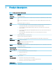
1 Product description Table 1-1 Product components and descriptions Category Description Product Name HP Chromebook 14A G5 Processors AMD® A6-9220C 1.8-GHz (turbo up to 2.7-GHz) dual core processor (R5-720, 1866-MHz FSB, 1.0-MB L2 cache, 6 W) AMD A4-9120C 1.6-GHz (turbo up to 2.4-GHz) dual core processor (R4-600, 1866-MHz FSB, 1.0-MB L2 cache, 6 W) Chipset AMD integrated soldered-on-circuit (SoC) Panel ● 14.
2 External component identification Right side Table 2-1 Right-side components and descriptions Component (1) Description Audio-out (headphone)/audio-in (microphone) combo jack Connects optional powered stereo speakers, headphones, earbuds, a headset, or a television audio cable. Also connects an optional headset microphone. This jack does not support optional standalone microphones. WARNING! To reduce the risk of personal injury, adjust the volume before putting on headphones, earbuds, or a headset.
Table 2-1 Right-side components and descriptions (continued) Component Description ● (5) USB Type-C power connector and port Off: The battery is not charging. Connects an AC adapter that has a USB Type-C connector, supplying power to the computer and, if needed, charging the computer battery. – and – Connects a USB device that has a Type-C connector, such as a cell phone, camera, activity tracker, or smartwatch, and provides data transfer.
Left side Table 2-2 Left-side components and descriptions Component (1) Description Security cable slot Attaches an optional security cable to the computer. NOTE: The security cable is designed to act as a deterrent, but it may not prevent the computer from being mishandled or stolen.
Display Table 2-3 Display components and descriptions Component Description (1) WLAN antennas* Send and receive wireless signals to communicate with wireless local area networks (WLANs). (2) Internal microphones (2) Record sound. (3) Camera light On: The camera is in use. (4) Camera Allows you to video chat, record video, and record still images. *The antennas are not visible from the outside of the computer, and antenna location varies.
Bottom Table 2-4 Bottom components and descriptions Components Description Vent Enables airflow to cool internal components. NOTE: The computer fan starts up automatically to cool internal components and prevent overheating. It is normal for the internal fan to cycle on and off during routine operation.
Speaker and buttons Table 2-5 Speaker and button components and descriptions Component Description (1) Speaker Produces sound. (2) Power button ● When the computer is off, press the button to turn on the computer. ● When the computer is on, press the button briefly to initiate Sleep. ● When the computer is in the Sleep state, press the button briefly to exit Sleep (select products only). ● When the computer is in Hibernation, press the button briefly to exit Hibernation.
Keyboard area Touchpad Table 2-6 Touchpad components and descriptions 8 Component Description Touchpad zone Reads your finger gestures to move the pointer or activate items on the screen.
Special keys Table 2-7 Special key components and descriptions Component Description (1) esc key Activates certain computer functions when pressed in combination with other keys, such as tab or shift. (2) Action keys Execute frequently used system functions.
Labels The labels affixed to the computer provide information you may need when you troubleshoot system problems or travel internationally with the computer. Labels may be in paper form or imprinted on the product. IMPORTANT: Check the following locations for the labels described in this section: the bottom of the computer, inside the battery bay, under the service door, on the back of the display, or on the bottom of a tablet kickstand.
Table 2-9 Label components and descriptions (continued) Component (3) Serial number (4) Warranty period ● Regulatory label(s)—Provide(s) regulatory information about the computer. ● Wireless certification label(s)—Provide(s) information about optional wireless devices and the approval markings for the countries or regions in which the devices have been approved for use.
3 Illustrated parts catalog Computer major components NOTE: HP continually improves and changes product parts. For complete and current information on supported parts for your computer, go to http://partsurfer.hp.com, select your country or region, and then follow the on-screen instructions.
Table 3-1 Computer component descriptions and spare part information Item Component (1) Display assembly: The display assembly is spared at the subcomponent level only. For more display assembly spare part information, see Display components on page 17.
Table 3-1 Computer component descriptions and spare part information (continued) Item Component Spare part number For use in Brazil L14354-201 For use in Canada L14354-DB1 For use in the Czech Republic and Slovakia L14354-FL1 For use in Denmark, Finland, and Norway L14354-DH1 For use in France L14354-051 For use in Germany L14354-041 For use in Iceland L14354-DD1 For use in Israel L14354-BB1 For use in Italy L14354-061 For use in Latin America L14354-161 For use in the Netherlands L1
Table 3-1 Computer component descriptions and spare part information (continued) Item Component Spare part number For use in Italy L14355-061 For use in Latin America L14355-161 For use in the Netherlands L14355-B31 For use in Portugal L14355-131 For use in Romania L14355-271 For use in Russia L14355-251 For use in Saudi Arabia L14355-171 For use in South Korea L14355-AD1 For use in Spain L14355-071 For use in Switzerland L14355-BG1 For use in Taiwan L14355-AB1 For use in Thailand
Table 3-1 Computer component descriptions and spare part information (continued) Item Component Spare part number Equipped with an AMD A4-9120C 2.2-GHz (turbo up to 2.5-GHz) quad core processor (2133MHz FSB, 8.0-MB L3 cache, 15 W), and 32-GB of eMMC memory L62473-001 For use only on computer models NOT equipped with a keyboard with backlight: Equipped with an AMD A6-9220C 2.2-GHz (turbo up to 2.5-GHz) quad core processor (2133MHz FSB, 8.
Display components Table 3-2 Display component descriptions and spare part information Item Component Spare part number (1) Display bezel L14335-001 (2) Webcam/microphone module (includes double-sided adhesive) L46567-001 (3) Display bracket L14337-001 (4) Display panel: 14.0-inch, FHD (1920×1080), BrightView, WLED, LCD, UWVA, 45, 220 nits, eDP, slim TouchScreen display assembly L46550-001 14.
Table 3-2 Display component descriptions and spare part information (continued) Item Component Spare part number (7) Webcam/microphone module cable L46566-001 (8) Display TouchScreen cable L15395-001 (9) Wireless Antenna Kit (includes left and right wireless antenna cables and transceivers) L46566-001 (10) Display back cover L46563-001 Miscellaneous parts Table 3-3 Miscellaneous component descriptions and spare part information Component Spare part number 45-W, non-PFC, USB Type-C AC adapte
Table 3-3 Miscellaneous component descriptions and spare part information (continued) Component Spare part number For use in South Korea L19366-001 For use in Switzerland L19370-001 For use in Taiwan L19372-001 For use in Thailand L19371-001 For use in United Kingdom L19373-001 Screw Kit L18112-001 Miscellaneous parts 19
4 Removal and replacement procedures preliminary requirements Tools required You will need the following tools to complete the removal and replacement procedures: ● Flat-bladed screwdriver ● Magnetic screwdriver ● Phillips P0 and P1 screwdrivers Service considerations The following sections include some of the considerations that you must keep in mind during disassembly and assembly procedures.
Cables and connectors CAUTION: When servicing the computer, be sure that cables are placed in their proper locations during the reassembly process. Improper cable placement can damage the computer. Cables must be handled with extreme care to avoid damage. Apply only the tension required to unseat or seat the cables during removal and insertion. Handle cables by the connector whenever possible. In all cases, avoid bending, twisting, or tearing cables.
Electrostatic discharge damage Electronic components are sensitive to electrostatic discharge (ESD). Circuitry design and structure determine the degree of sensitivity. Networks built into many integrated circuits provide some protection, but in many cases, ESD contains enough power to alter device parameters or melt silicon junctions. A discharge of static electricity from a finger or other conductor can destroy static-sensitive devices or microcircuitry.
Packaging and transporting guidelines Follow these grounding guidelines when packaging and transporting equipment: ● To avoid hand contact, transport products in static-safe tubes, bags, or boxes. ● Protect ESD-sensitive parts and assemblies with conductive or approved containers or packaging. ● Keep ESD-sensitive parts in their containers until the parts arrive at static-free workstations. ● Place items on a grounded surface before removing items from their containers.
Equipment guidelines Grounding equipment must include either a wrist strap or a foot strap at a grounded workstation. ● When seated, wear a wrist strap connected to a grounded system. Wrist straps are flexible straps with a minimum of one megohm ±10% resistance in the ground cords. To provide proper ground, wear a strap snugly against the skin at all times. On grounded mats with banana-plug connectors, use alligator clips to connect a wrist strap.
5 Removal and replacement procedures This chapter provides removal and replacement procedures for Authorized Service Provider only parts. CAUTION: Components described in this chapter should only be accessed by an authorized service provider. Accessing these parts can damage the computer or void the warranty. CAUTION: This computer does not have user-replaceable parts. Only HP authorized service providers should perform the removal and replacement procedures described here.
Table 5-1 Keyboard/top cover description and spare part number information (continued) For use in country/ region Spare part number For use in country/ region Spare part number For use in country/ region Spare part number For use in Brazil L14355-201 For use in Italy L14355-061 For use in Spain L14355-071 For use in Canada L14355-DB1 For use in Latin America L14355-161 For use in Switzerland L14355-BG1 For use in the Czech Republic and Slovakia L14355-FL1 For use in the Netherlands L143
2. Remove the following: (1) Two rear rubber feet (2) Three flat rubber screw covers (3) Four wedge-shaped screw covers NOTE: The rubber feet and the screw covers are included in the Rubber Kit, spare part number L14351-001. 3. Remove the two Phillips M2.5×9.1 screws (1) that secure the keyboard/top cover to the base enclosure.
4. Remove the seven Phillips M2.5×6.6 screws (2) that secure the keyboard/top cover to the base enclosure. 5. Place the computer right side up with the front toward you. 6. Open the computer. 7. Insert a case utility tool (1) or similar thin, plastic tool into the keyboard/top cover front edge. 8. Lift up on the keyboard/top cover front edge (2) until it separates from the base enclosure. 9.
11. Remove the keyboard/top cover (5). Reverse this procedure to install the keyboard/top cover.
Touchpad cable NOTE: The touchpad spare part kit does not include the touchpad cable. The touchpad cable is included in the Cable Kit, spare part number L14330-001. Before removing the touchpad cable, follow these steps: 1. Shut down the computer. If you are unsure whether the computer is off or in Hibernation, turn the computer on, and then shut it down through the operating system. 2.
Touchpad NOTE: The touchpad spare part kit does not include the touchpad bracket or touchpad cable. The touchpad bracket is available using spare part number L18436-001. The touchpad cable is included in the Cable Kit, spare part number L14330-001. Table 5-2 Touchpad description and spare part number information Description Spare part number Touchpad L46559-001 Before removing the touchpad, follow these steps: 1. Shut down the computer.
6. Remove the touchpad (6). Reverse this procedure to install the touchpad.
Battery Table 5-3 Battery description and spare part number information Description Spare part number 2-cell, 47 Whr, 6.15 Ahr, Li-ion battery (includes cable) L42583-005 Before removing the battery, follow these steps: 1. Shut down the computer. If you are unsure whether the computer is off or in Hibernation, turn the computer on, and then shut it down through the operating system. 2. Disconnect all external devices connected to the computer. 3.
WLAN module Table 5-4 WLAN module description and spare part number information Description Spare part number Qualcomm Atheros QCA6174A-5 ac 2×2 + Bluetooth 4.2 M.2 2230 PCI-e WW with 2 antennas L54597-001 CAUTION: To prevent an unresponsive system, replace the wireless module only with a wireless module authorized for use in the computer by the governmental agency that regulates wireless devices in your country or region.
Connector board cables NOTE: The connector board spare part kit does not include the connector board cables. The connector board cables are included in the Cable Kit, spare part number L14330-001. Before removing the connector board cables, follow these steps: 1. Shut down the computer. If you are unsure whether the computer is off or in Hibernation, turn the computer on, and then shut it down through the operating system. 2.
Connector board NOTE: The connector board spare part kit does not include the connector board bracket or connector board cable. The connector board bracket is available using spare part number L14359-001. The connector board cables are included in the Cable Kit, spare part number L14330-001..
6. Remove the connector board (6). Reverse this procedure to install the connector board.
Speakers Table 5-6 Speakers description and spare part number information Description Spare part number Speakers (include left and right speakers and cables) L14353-001 Before removing the speakers, follow these steps: 1. Turn off the computer. If you are unsure whether the computer is off or in Hibernation, turn the computer on, and then shut it down through the operating system. 2.
Infrared sensor board cable NOTE: The infrared sensor board spare part kit does not include the infrared sensor board cable. The infrared sensor board cable is included in the Cable Kit, spare part number L14330-001. Before removing the infrared sensor board cable, follow these steps: 1. Shut down the computer. If you are unsure whether the computer is off or in Hibernation, turn the computer on, and then shut it down through the operating system. 2.
Infrared sensor board NOTE: The infrared sensor board spare part kit does not include the infrared sensor board cable. The infrared sensor board cable is included in the Cable Kit, spare part number L14330-001. Table 5-7 Infrared sensor board description and spare part number information Description Spare part number Infrared sensor board L46558-001 Before removing the infrared sensor board, follow these steps: 1. Shut down the computer.
System board NOTE: The system board spare part kit includes a graphics subsystem with UMA memory, 4-GB of system memory, the Chrome operating system, and replacement thermal material. Table 5-8 System board description and spare part number information Description Spare part numbers For use only on computer models equipped with a backlight: Equipped with an AMD A6-9220C 2.2-GHz (turbo up to 2.5-GHz) quad core processor (2133-MHz FSB, 8.
3. Release the adhesive support strip (3) that secures the display panel cable to the system board. 4. Disconnect the display panel cable (4) from the system board. 5. Disconnect the speaker cable (5) from the system board. 6. Release the adhesive strip (6) that secure the speaker cable to the system board. 7. Remove the six Phillips M2.0×4.2 screws (1) that secure the system board to the base enclosure. 8. Remove the I/O bracket (2). The I/O bracket is available using spare part number . 9.
10. Remove the system board (4) by sliding it up and to the left at an angle. Reverse this procedure to install the system board.
Heat sink Table 5-9 Heat sink description and spare part number information Description Spare part number Heat sink (includes replacement thermal material) L46576-001 Before removing the heat sink, follow these steps: 1. Turn off the computer. If you are unsure whether the computer is off or in Hibernation, turn the computer on, and then shut it down through the operating system. 2.
NOTE: The thermal material must be thoroughly cleaned from the surfaces of the heat sink and the system board components each time the heat sink is removed. Replacement thermal material is included with the heat sink and system board spare part kits. Thermal paste is used on the processor (1) and the heat sink section (2) that services it. Reverse this procedure to install the heat sink.
Display assembly NOTE: The display assembly is spared at the subcomponent level. For display assembly spare part information, see the individual removal subsections. Before removing the display assembly, follow these steps: 1. Shut down the computer. If you are unsure whether the computer is off or in Hibernation, turn the computer on, and then shut it down through the operating system. 2. Disconnect all external devices connected to the computer. 3.
7. Release the WLAN antenna main cable from the retention clips (8) and routing channel built into the keyboard/top cover. 8. If it is necessary to replace the display bezel or any of the display assembly subcomponents: a. Swing the inside edge of the display bezel top edge (1) up and back until it releases from the display back cover. b. Swing the inside edges of the display bezel left and right edges (2) up and out until they release from the display back cover.
d. Remove the display bezel (5). The display bezel is available using spare part number L14335-001. 9. 48 If it is necessary to replace the webcam/microphone module: a. Remove the display bezel. b. Detach the webcam/microphone module (1) from the display back cover. (The webcam/microphone module is attached to the display back cover with double-sided adhesive.
c. Disconnect the webcam/microphone module cable (2) from the webcam/microphone module. The webcam/microphone module is available using spare part number L46567-001. 10. If it is necessary to replace the display panel: a. Remove the display bezel. b. Remove the four Phillips M2.0×2.8 screws (1) that secure the display panel to the display back cover. c. Lift the display panel top edge (2) and swing it up and forward until it rests upside down in front of the display back cover.
d. Release the display panel cable from the retention clips (1) and routing channel built into the display back cover. e. Release the adhesive support strip (2) that secures the display panel cable to the display panel. f. Disconnect the display panel cable (3) from the display panel. g. Remove the display panel. The display panel is available using the following spare part numbers: L46548-001 – 14.
e. Release the display panel cable and the wireless antenna main cable from the right hinge area (5). f. Remove the display back cover (6). The display panel is available using spare part number L46563-001. 12. If it is necessary to replace the display panel cable: a. Remove the display bezel. b. Release the display panel. c. Release the display back cover. d. Once the display back cover is removed, the display panel cable is removed.
f. Remove the display hinges (3). The display hinges are available using spare part number L14332-001. 14. If it is necessary to replace the webcam/microphone module cable: a. Remove the display bezel. b. Release the display panel. c. Release the display back cover. d. Disconnect the webcam/microphone module cable (1) from the webcam/microphone module. e.
15. If it is necessary to replace the wireless antenna: a. Remove the display bezel. b. Release the display panel. c. Release the display back cover. d. Detach the wireless antenna transceivers (1) from the display back cover. (The wireless antenna transceivers are attached to the display back cover with double-sided adhesive.) e. Release the wireless antenna cables from the retention clips (2) and routing channel built into the top, left and right, and bottom edges of the display back cover. f.
6 Specifications Computer specifications Metric U.S. Width 33.7 cm 13.3 inches Depth 22.7 cm 8.9 inches Height (front to back) 1.8 centimeters 0.72 inches Weight 1.6 kg 3.5 lbs Dimensions Input power Operating voltage and current 19.5 V dc @ 3.33 A – 65 W 19 V dc @ 4.62 A – 90 W 19.5 V dc @ 2.
7 Power cord set requirements The wide-range input feature of the computer permits it to operate from any line voltage from 100 to 120 V AC, or from 220 to 240 V AC. The 3-conductor power cord set included with the computer meets the requirements for use in the country or region where the equipment is purchased. Power cord sets for use in other countries or regions must meet the requirements of the country and region where the computer is used.
Requirements for specific countries and regions 56 Country/region Accredited agency Applicable note number Argentina IRAM 1 Australia SAA 1 Austria OVE 1 Belgium CEBEC 1 Brazil ABNT 1 Canada CSA 2 Chile IMQ 1 Denmark DEMKO 1 Finland FIMKO 1 France UTE 1 Germany VDE 1 India BIS 1 Israel SII 1 Italy IMQ 1 Japan JIS 3 The Netherlands KEMA 1 New Zealand SANZ 1 Norway NEMKO 1 The People's Republic of China CCC 4 Saudi Arabia SASO 7 Singapore PSB
Country/region Accredited agency Applicable note number 3. The appliance coupler, flexible cord, and wall plug must bear a “T” mark and registration number in accordance with the Japanese Dentori Law. The flexible cord must be Type VCTF, 3-conductor, 0.75 mm² or 1.25 mm² conductor size. The wall plug must be a twopole grounding type with a Japanese Industrial Standard C8303 (7 A, 125 V AC) configuration. 4. The flexible cord must be Type RVV, 3-conductor, 0.75 mm² conductor size.
8 Recycling When a non-rechargeable or rechargeable battery has reached the end of its useful life, do not dispose of the battery in general household waste. Follow the local laws and regulations in your area for battery disposal. HP encourages customers to recycle used electronic hardware, HP original print cartridges, and rechargeable batteries. For more information about recycling programs, see the HP Web site at http://www.hp.com/recycle.
Index A AC adapter light 2 AC adapter, spare part number 18 action keys identifying 9 adapter, spare part numbers 18 antenna removal 53 spare part number 53 antenna, spare part number 18 audio, product description 1 audio-in (microphone) jack, identifying 2 audio-out (headphone) jack, identifying 2 B backpack, spare part number 18 base enclosure spare part number 16 battery light 2 removal 33 spare part number 15, 33 Bluetooth label 11 buttons power 7 C camera light, identifying 5 camera, identifying 5 chip
K keyboard/top cover removal 25 spare part numbers keys esc 9 13, 14, 25 L labels Bluetooth 11 regulatory 11 serial number 10 service 10 wireless certification 11 WLAN 11 lights AC adapter and battery 2 camera 5 lock, spare part number 18 M memory, product description 1 microphone product description 1 microphone (audio-in) jack, identifying 2 microSD memory card reader, identifying 2 model name 1 mouse, spare part numbers 18 Mylar Kit, spare part number 18 requirements for specific countries and regions
wireless antenna removal 53 spare part number 53 wireless antenna, spare part number 18 wireless certification label 11 wireless, product description 1 WLAN spare part number 15 WLAN antenna removal 53 spare part number 53 WLAN antenna, spare part number 18 WLAN antennas, identifying 5 WLAN device 11 WLAN label 11 WLAN module removal 34 spare part number 34 workstation guidelines 23 Index 61