
Maintenance and Service Guide

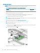

Connector board
NOTE: The connector board spare part kit does not include the connector board bracket or connector
board cable. The connector board bracket is available using spare part number L14359-001. The connector
board cables are included in the Cable Kit, spare part number L14330-001..
Table 5-5 Connector board description and spare part number information
Description Spare part number
Connector board (includes USB port and USB Type-C port) L46557-001
Before removing the connector board, follow these steps:
1. Shut down the computer. If you are unsure whether the computer is o or in Hibernation, turn
the computer on, and then shut it down through the operating system.
2. Disconnect all external devices connected to the computer.
3. Disconnect the power from the computer by rst unplugging the power cord from the AC outlet, and then
unplugging the AC adapter from the computer.
4. Remove the keyboard/top cover (see Keyboard/top cover on page 25).
5. Disconnect the battery cable from the system board (see Battery on page 33).
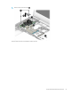
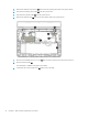
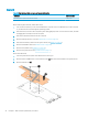
Remove the connector board:
1. Release the ZIF connectors (1) to which the connector board cables are connected, and then disconnect
the connector board cables from the system board.
2. Detach the connector board cables (2) from the base enclosure. (The connector board cables are attached
to the base enclosure with double-sided adhesive.)
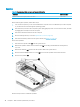
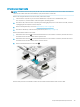
3. Release the ZIF connector (3) to which infrared sensor board cable is connected, and then disconnect
the infrared sensor board cable from the system board.
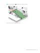
4. Remove the two Phillips M2.0×4.2 screws (4) that secure the connector board and connector board bracket
to the base enclosure.
5. Remove the connector board bracket (5).
36 Chapter 5 Removal and replacement procedures