
User's Manual


I
-
Using Spectrum Analyzer Features
Using Limit-Line Functions
l With the lower limit-line table format, one amplitude component
(representing a lower limit-line segment) is specified per
frequency/time component. The amplitude value is entered by pressing
SELECT
AMPLITUD
, entering an amplitude value, and pressing a units key.
l With the upper/lower limit-line table format, two amplitude components
(one each for the upper and lower limit-line segments) can be specified
per frequency or time component. It is not necessary to specify both
an upper and a lower amplitude value. Specifying only upper amplitude
values results in an upper limit line, but not a lower limit line. Omitting
an amplitude point on one limit line does not affect the other limit
line. The amplitude of the upper limit line is entered by pressing
SELECT
UPR
AMPL , entering an amplitude value, and pressing a
units key. The amplitude of the lower limit line is entered by pressing
SELECT
LWR
AMPL , entering an amplitude value, and pressing a units key.
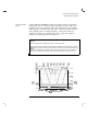
l With the mid/delta limit-line table format, two amplitude components
(one representing a mid-amplitude value, one representing a deviation
[positive and negative values] from either side of this value) is specified
per frequency component. If no deviation is entered, the deviation
defaults to zero. The middle amplitude value is entered by pressing
SELECT MID AMPL , entering an amplitude value, and pressing a units
key. The deviation is entered by pressing SELECT DLT AMPL , entering an
amplitude value, and pressing a units key.
NOTE
Frequency or amplitude values that are not within the limit-line range will be modified. For example, a
frequency value of 3
GHz
will be modified to 1.9
GHz.
3-45
I-