HP A8800 Routers Installation Guide Part number: 5998-1416 Document version: 6W104-20130912
Legal and notice information © Copyright 2011-2013 Hewlett-Packard Development Company, L.P. No part of this documentation may be reproduced or transmitted in any form or by any means without prior written consent of Hewlett-Packard Development Company, L.P. The information contained herein is subject to change without notice.
Contents Preparing for installation ············································································································································· 1 Overview············································································································································································ 1 Safety recommendations ······························································································································
Displaying the operating state of a fan ······················································································································· 37 Displaying alarm information for a card ····················································································································· 37 Verifying and diagnosing transceiver modules ·········································································································· 38 Introduction to transceiver modul
Transceiver modules··················································································································································· 89 10-GE XFP transceiver modules ···································································································································· 89 FE/GE SFP transceiver modules ··································································································································· 90 OC-48/STM-
Preparing for installation Overview This series is a line of data center routers. You can deploy the A8800 routers at the core layer and distribution layer of large-scale MANs, the core layer of enterprise networks, and the distribution layer of carrier networks. Table 1 lists the chassis models in the series.
Installation site requirements The following tables provide information about temperature and humidity, cleanness, and air quality requirements. CAUTION: If condensation appears on the router when you move it to a high-temperature environment, dry the router before powering it on to avoid short circuits. To ensure normal operation of the router, make sure the room temperature meets the requirements described in Table 2.
Rack-mounting requirements Before rack-mounting a router, make sure the rack meets the following requirements: • HP recommends that the router is mounted in an open rack. If you mount a router in a closed rack, make sure there is a good heat dissipation system. • The rack is steady enough to support the router and accessories. • The router fits the rack size. Leave some space beside the left and right panels of the router for chassis heat dissipation.
The rack accessories and installation tools are not described in this section. The accessories and installation tools may vary depending on the rack model. For more information, see the installation guide for the corresponding rack.
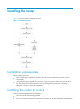
Installing the router Figure 1 shows the steps for installing the router. Figure 1 Installation flowchart Installation prerequisites Before installing the router: • Read "Preparing for installation" carefully and make sure the installation site meets all of the requirements. • Using the packing list supplied with your router, inspect the router to make sure you have all of the items listed and verify that the router was not damaged during shipment.
• There is no debris inside or around the rack. • The router can be installed only in a 4-post 19-inch standard rack. Mounting slide rails to the rack If the rack already has slide rails, skip this section. Slide rails or rack shelves are not provided with the router. Prepare them yourself or order them from HP. Make sure the slide rails or rack shelves you use are standard accessories. In addition to slide rails, you can use a rack shelf to support the router.
NOTE: The appearance and installation methods of slide rails depend on the slide rail types. Installing cage nuts to the rack Before mounting the chassis to the rack, install cage nuts to the front square-holed brackets of the rack, as shown in Figure 3. When preparing for installation, make sure the total height of the routers to be installed does not exceed the height of the rack, and reserve enough clearance for cable routing. 1.
To install a cable management bracket: 1. Attach the cable management bracket to the chassis, and align the screw holes on the cable management bracket with the screw holes on the chassis, as shown in Figure 4. 2. Screw in and fasten the M4 screws with a screwdriver.
Figure 5 Installing the cable management bracket on the A8805/A8812 Installing the mounting brackets Before installing the router to the rack, install the mounting brackets to the chassis. Figure 6 shows how to install the mounting brackets to an A8805 router.
Installing an impedance carrier (optional) An impedance carrier is shipped with the A8808 only. You can install the impedance carrier at the rear of the chassis (where an air filter is located) to block the airflow from entering the rear of the chassis. Install an impedance carrier for routers that have front-to-rear airflow, as shown in Figure 7. To install an impedance carrier: 1. Loosen the captive screws on the air filter to remove the air filter. 2.
that the bottom edge of the slide rail aligns with the middle of the narrowest metal area between holes, and that the cage nuts are installed in the correct holes. Figure 8 Installing the router in a standard 19-inch rack Verifying the installation Use the following checklist to make sure the router has been installed correctly. Table 6 Installation checklist Result Item Yes No Remarks Mounting brackets are firmly attached to the router. The router is installed in the correct position.
3. Insert the grounding screw into the grounding hole and tighten the screw. 4. Connect the other end of the grounding cable to the grounding strip of the rack in the same way. Figure 9 Connecting the grounding cable If there is no grounding point on the rack, you can attach the grounding cable to a grounding strip. The installation procedures are similar. Installing the power system CAUTION: Hold a power supply by the bottom when moving it.
Installing a DC power supply 1. Remove the air filter frame of the power supply and gently pull the DC power supply handle out. 2. Holding the handle of the power supply with one hand and supporting the bottom of the power supply with the other hand, push the power supply slowly along the slide rails until it makes close contact with the backplane, as shown in Figure 10. 3. Fasten the mounting screws on the power supply panel with a Phillips screwdriver. 4.
Installing an NEPS1800-A AC power supply 1. Pull the handle of the power supply downward to the unlock position. 2. Gently push the power supply into the AC power frame (NEPS3500-A) until the rear side of the power supply makes close contact with the power frame backplane. 3. Push the handle upward so that it locks the power supply in place. Figure 12 Installing an AC power supply Installing a card All cards (excluding subcards) for the routers are hot-swappable.
Figure 13 Removing the protection cover 2. Move the ejector levers of the card outward. Supporting the bottom of the card with both hands, slowly push the card into the slot along the slide rails. 3. Push the ejector levers inward to ensure close contact between the card and the backplane. 4. Position the screws in the holes and fasten them with a screwdriver to attach the card.
3. Remove the blank panel (if any) from the slot to be used on the SPE card. 4. Unpack the subcard. To install a subcard: 1. Turn the ejector levers of the subcard outward simultaneously with both hands, and then slide the subcard (with the right side up) straight into the SPE card along the slide rails until the ejector levers touch the panel of the SPE card, as shown in Figure 15. 2. Push against the front panel of the subcard.
Connecting an AC power cable CAUTION: NEPS3500-A requires a 16 A power cable (AC), so you must use a 16 A busbar and make sure the AC power source can provide enough power. The following procedure uses the AC power supply that comprises one 3500 W AC power frame and two 1800 W power supplies to show how to install AC power cables. To connecting an AC power cable: 1. Insert the ends of the bail latch into the holes on the left side of the upper power supply. 2.
WARNING! To protect operators from being shocked, install the protection cover over the DC terminal block immediately after you connect the power cables. To connect the DC power cables: 1. Remove the protection cover of the DC terminal block from the DC power supply. 2. Loosen the fastening screws on the top two terminals with a Phillips screwdriver. 3. Connect one end of the blue –48 VDC power cable to the negative terminal (–) on the power supply and fasten the screw.
Verifying the installation WARNING! Before verifying the installation, make sure you have turned off the power to avoid bodily injury and router damage. Use the following checklist to make sure the router has been installed correctly. Table 7 Installation checklist Item Result Yes The grounding cable is grounded correctly. Power supplies are installed correctly and firmly seated. Power cables are connected correctly. MPUs are installed correctly and have close contact with the backplane.
Connecting the router to the network Logging in to the router The most common way to log in to a router is through the console port. It is also the prerequisite to configuring other login methods. Connecting the console cable A console cable is an 8-core shielded cable, with a crimped RJ-45 connector at one end for connecting to the console port of the router, and a DB-9 female connector at the other end for connecting to the serial port on the console terminal, as shown in Figure 18.
Figure 19 Connecting the router and the PC through the console port To connect the console cable: 1. Connect the DB-9 connector of the console cable to the serial port of a PC or terminal. 2. Connect the RJ-45 connector of the console cable to the console port of the MPU of the router. 3. When you remove the console cable, first unplug the RJ-45 end, and then unplug the DB-9 end. Setting up a configuration environment 1.
Figure 20 Connection Description dialog box for HyperTerminal 2. Enter the name of the new connection in the Name box, and then click OK. The system displays the interface, as shown in Figure 21.
Figure 21 Selecting a port for the HyperTerminal connection 3. Select a port from the Connect using list, and then click OK. 4. Set the Bits per second to 9600, Data bits to 8, Parity to None, Stop bits to 1, and Flow control to None, and click OK.
Figure 22 Setting the serial port parameters 24
Figure 23 HyperTerminal window 5. Select File > Properties in the HyperTerminal window. 6. On the Settings tab, select VT100 for terminal emulation, and click OK. NOTE: HP recommends that you select the Windows keys option.
Figure 24 Setting the terminal emulation parameters Powering on the router CAUTION: Before powering on the router, locate the power switch in the equipment room so that you can disconnect the power supply promptly in case of an emergency. Before powering on the router, confirm the following: • The interface cables, power cables, and grounding cable are connected correctly. • The power outlet voltage is the same as indicated on the router label.
2. Turn on the power switch on the router. Before the router is powered on, the following information is displayed: DDR2 SDRAM test successful. System is starting... Booting Normal Extend BootWare The Extend BootWare is self-decompressing.......................... Done! **************************************************************************** * * * HP A8800 BootWare, Version 1.
kbd->bi_immr_base = 0xff700000. Starting kernel at 0x10000 ... Now beginning to initialize system User interface con0 is available. After the router completes booting the applications, the following information appears on the terminal screen: Press ENTER to get started. 3. Press Enter to begin configuring the router at the prompt: NOTE: • The router displays a CLI. For more information about the CLI, see HP A8800 Routers Fundamentals Configuration Guide. • The output depends on your router model.
Connecting through an AUX cable You need an AUX cable when configuring a router using a remote dial-up modem. An AUX cable is an 8-core shielded cable. At one end of the cable is an RJ-45 connector. At the other end is a DB-9 (male) connector. An AUX cable is the same as a console cable. For more information, see Figure 18 and Table 8. To connect the AUX port: 1. Plug the RJ-45 connector of the AUX cable into the AUX port of the router. 2.
Installing a transceiver module CAUTION: During installation, do not touch the golden finger of the SFP module. The installation procedures for an XFP module and SFP module are similar. The following procedure uses an SFP module as an example. To install an SFP module: 1. Put on an ESD-preventive wrist strap, and make sure it makes good skin contact, and is well grounded. 2. Unpack the SFP module.
Figure 27 Connecting an optical fiber to an SFP module Installing an FMT (optional) The FMT is installed in a cabinet for winding redundant fibers between the router and other devices. Confirm the following prerequisites: • The cabinet is attached. • The router is installed. The installation involves the following materials: • FMT • M5×10 self-tapping screws (two screws for one FMT) To install the FMT: 1. Align the FMT and the installation holes on the column of the cabinet. 2.
CAUTION: Do not bind cables at the air exhaust vent to prevent the cables from aging too fast. For more information, see "Cable management." Interface cables and power cables should be routed separately. Proper cable routing can improve efficiency by facilitating installation and removal of fan trays, the PEM, and other components.
Hardware management This chapter describes the hardware management functions of the router. Displaying electrical label data Electrical label data is also called permanent configuration data or archive information, which is written to the storage component of a card during device debugging or testing. The information includes name of the card, card serial number, and vendor name.
6 NONE Absent NONE Table 10 Command output Field Description Slot No. Slot number of a card. Hardware type of a card: Specific card model, such as SPE-1010-II, which is the same as the mark on the card. Brd Type • NONE—No card is in the slot. • UNKNOWN—The card is not supported by the software version and cannot start normally. Card status: Brd Status • • • • • • Absent—No card is in the slot. Master—The card is an AMB. Slave—The card is a SMB.
Step Command Remarks Optional. Available in user view. 1. Reboot a card, or the whole system immediately. reboot [ slot slot-number ] The precision of the rebooting timer is 1 minute. One minute before the rebooting time, the router prompts "REBOOT IN ONE MINUTE" and reboots in one minute. If you do not specify the slot keyword, or reboot the AMB, the reboot command reboots the router.
Configuring temperature alarm thresholds for a card Use the following command to set temperature alarm thresholds for a card. When the temperature of a card exceeds a threshold, the router generates alarm signals. To configure temperature alarm thresholds for a card: Step Command Remarks 1. Enter system view. system-view N/A 2. Configure temperature alarm thresholds for a card. temperature-limit slot slot-number hotspot sensor-num LowerLimit WarningLimit [ AlarmLimit ] Optional.
The in-service hardware failure diagnosis includes the detection for chips, cards, and the forwarding service, and automatic fix actions taken for the detected failures. To configure in-service hardware failure diagnosis: Step 1. Enter system view. Command Remarks system-view N/A Required. The fix actions taken in case of hardware failures include: 2. Enable in-service hardware failure detection and configure fix actions taken in case of hardware failures.
Field Description Info Detailed alarm information. Slot n board state is faulty. Card n is faulty. The reason may be the card is booting or the card fails. Verifying and diagnosing transceiver modules Introduction to transceiver modules There are two types of commonly used transceiver modules, as shown in Table 14. They can be further divided into optical transceiver modules and electrical transceiver modules based on transmission medium.
Digital Diagnostic Monitoring : YES Vendor Name : HP Ordering Name : JD118B Table 15 Command output Field Description transceiver information Transceiver information Transceiver Type Transceiver type Type of connector: Connector Type • Optical connectors, including SC (SC connector, developed by NTT) and LC (LC connector, 1.25 mm/RJ-45 optical connector developed by Lucent). • Other connectors, including RJ-45 and CX 4. • Optical transceiver module—Central wavelength of the laser sent, in nm.
Diagnosing transceiver modules The device provides the alarm function and digital diagnosis function for transceiver modules. When a transceiver module fails or inappropriately work, you can check for alarms present on the transceiver module to identify the fault source or examine the key parameters monitored by the digital diagnosis function, including the temperature, voltage, laser bias current, TX power, and RX power.
Field Remarks XFP RX loss of signal RX signal is lost. RX not ready RX is not ready. RX CDR loss of lock RX clock cannot be recovered. TX fault TX fault. TX not ready TX is not ready. TX CDR loss of lock TX clock cannot be recovered. Module not ready Module is not ready. APD supply fault Avalanche Photo Diode (APD) supply fault. TEC fault Thermoelectric Cooler (TEC) fault. Wavelength unlocked Wavelength of optical signal exceeds the manufacturer's tolerance.
Table 18 Command output Field Description Transceiver diagnostic information Fault detection information of the transceiver module plugged in the interface Current diagnostic parameters Current fault detection parameters Temp.(°C) Digital diagnosis parameter-temperature, in °C, with the precision to 1°C Voltage(V) Fault detection parameter-voltage, in V, with the precision to 0.01 V Bias(mA) Fault detection parameter-bias current, in mA, with the precision to 0.
Troubleshooting This chapter describes how to troubleshoot router installation failures. The router power supply system, fans, and cards have multiple LEDs to help you locate failures. Configuration terminal problems If the configuration environment setup is correct, the configuration terminal displays boot information when the router is powered on. If the setup is incorrect, the configuration terminal displays nothing or garbled text.
Table 19 AC power supply LED LED Input Output Fault Status Description Steady green Power is being input correctly. Off The power supply is absent or has input voltage error. Steady green The power supply is outputting power correctly. Off The power supply has an output voltage error or is absent. Steady red The power supply is experiencing an overvoltage, overcurrent, or overtemperature condition. Off The power module is operating correctly or absent.
Table 21 Fan LEDs LED RUN ALM Status Description Off The fan tray has failed. Steady green The fan tray is operating properly. Off The fan tray is in a normal state. Steady red The fan tray is faulty. When the RUN LED is off or the ALM LED is on, the fan tray fails. To troubleshoot the fan tray: 1. If both LEDs are off, examine the power supply to make sure it is operating properly. For more information, see "Power supply system failure." 2.
2. Press the MPU RESET button to reset the MPU, and then verify that the corresponding RUN LED is on. 3. Make sure the MPU is seated properly. You can unplug the MPU, plug it in again, and make sure the MPU is seated properly. 4. If the router has empty MPU slots, plug the MPU into an empty slot and make sure the MPU is operating properly. 5. If the ALM LED is on, the MPU reports alarms. Use the display alarm command to locate and resolve the failures. 6.
6. If the LED is for a copper or fiber combo port, make sure the port has been activated. If not, use the combo enable { copper | fiber } command to activate it. If the LED is still off, the interface or the link has failed. 7. Use the display interface command to determine if the interface is UP. If the interface is not UP, use the undo shutdown command to bring up the interface. 8. Make sure the speed and duplex settings of the link interfaces are the same, and the interfaces work properly together.
Replacement procedures This chapter provides information about replacing components on the router. Replacing a power supply system WARNING! • Power supplies for the router are hot-swappable. When hot-swapping a power supply, make sure the other power supply is operating properly. When installing and replacing a power supply with the router powered on, pay attention to the operation procedures and electricity safety issues.
Figure 30 Replacing a DC power supply (A) DC power supply to be removed (B) DC power supply to be installed Replacing an AC power supply 1. Pull the handle of the power supply downward to the unlock position. Gently move the power supply to separate it from the backplane of the power frame. 2. Supporting the bottom of the power supply with one hand and holding the power supply handle with the other hand, gently pull the power supply out.
5. Slowly push a new power frame into the slot along the slide rails until the rear of the power frame has close contact with the backplane. 6. Use a Phillips screwdriver to fasten the captive screws on both sides of the power frame. 7. Pull the handle of a power supply downward to the unlock position. 8. Gently push the power supply into the specified slot of the AC power frame until the rear of the power supply has close contact with the AC power frame backplane. 9.
Cleaning a power supply air filter To ensure proper ventilation of the power supply, HP recommends that you clear the air filter monthly. The NEPS3500-A power frame does not have an air filter. To clean the power supply air filter: 1. Using your thumb and index finger to hold the upper and lower edges of the air filter frame, gently remove the air filter frame. Pull the black air filter out of the air filter frame. Figure 32 Removing a power supply air filter 2.
2. Remove the blank panel (if any) from the slot to be used. Keep the removed blank panel and protection cover for future use. 3. Unpack the card to be installed. If the card has a protection cover, remove it. Keep the removed protection cover for future use. Figure 34 Removing the protection cover To replace a card: 1. Put on an ESD-preventive wrist strap and loosen the captive screws on both sides of the card to be removed. 2.
Figure 35 Replacing a card Replacing a subcard CAUTION: When the router is operating, you must remove the SPE card before removing or installing the subcard. Subcards do not support hot swapping. Replace a subcard using one of the following methods: • Power off the router, and then remove or install the subcard on the SPE card. • When the router is operating, remove the SPE card, replace the subcard on the SPE card, and then install the SPE card to the router.
Figure 36 Replacing a subcard (A) Subcard to be removed (B) Subcard to be installed Replacing a fan tray CAUTION: Fan trays are hot-swappable. If you replace a fan tray with the router running, pull out the fan tray after it stops rotating and keep your hands away from the spinning fan blades. To avoid injury, do not touch any wires, terminals, or parts with a high-voltage hazard sign.
3. Gently insert the new fan tray into the fan tray slot along the slide rails until it has close contact with the backplane. 4. Use a Phillips screwdriver to fasten the captive screws on both sides of the fan tray panel. Figure 37 Removing a fan tray for an A8805/A8812 Replacing a fan tray for an A8808 The fan tray for an A8808 is installed horizontally. To replace a fan tray for an A8808: 1. Use your thumb to press the fan tray button, and then pull the fan tray partway out. 2.
Figure 38 Replacing a fan tray for an A8808 (A) Fan tray to be removed (B) Fan tray to be installed Replacing a chassis air filter CAUTION: Clean the air filters every three months to guarantee adequate ventilation and avoid over-temperature. A chassis air filter is not shipped with the router. You can order one if needed. Replacing chassis air filters for an A8808 1. Use a Phillips screwdriver to remove the captive screws on the front and rear air filters, as shown in Figure 39. 2.
Figure 39 Replacing chassis air filters for an A8808 Replacing an air filter for an A8805/A8812 1. Loosen the captive screws on the air filter, as shown in Figure 40. 2. Grasping the captive screws on the air filter, slowly pull the air filter out of the chassis, as shown in Figure 40. 3. Install the cleaned air filter on the router. Figure 40 Replacing an air filter for an A8805 Replacing a CF card CAUTION: Do not remove the CF card when the router is booting or the CF card LED is flashing.
Figure 41 CF card slot (1) CF card cover (2) CF card eject button (3) CF card (4) CF card LED The CF card is installed on the MPU of the router. If the CF card memory is insufficient or the CF card is damaged, follow these steps to replace the card. Before inserting the CF card, make sure the eject button is all the way into the slot and does not project from the panel. 1. Examine the CF card LED status. { If the LED is on, you cannot remove the CF card.
Figure 42 Replacing a CF card Replacing a transceiver module CAUTION: When installing or removing an SFP transceiver module, do not touch the golden finger. The replacement procedures for XFP and SFP transceiver modules are similar. This section uses an SFP transceiver module as an example. To replace a transceiver module: 1. Put on an ESD-preventive wrist strap, ensuring that the wrist strap makes good skin contact and is grounded. 2.
Figure 43 Removing an SFP transceiver module Figure 44 Installing an SFP transceiver module 60
Hardware specifications Environmental requirements Table 22 Environment requirements Temperature Range Long term: 0°C to 45°C (32°F to 113°F) Operating temperature Short term: –10°C to +55°C (14°F to 131°F) (no more than 96 hours of continuous operation in less than 15 days in one year) Operating humidity (noncondensing) 5% to 95% Storage temperature –40°C to +70°C (–40°F to +158°F) Operating altitude Available altitude: ≤ 4000 m (13123.36 ft) Certificated altitude: ≤ 3000 m (9842.
Figure 45 A8805 front view (1) ESD-preventive wrist strap port (2) MPU slots (slots 0 and 1) (4) Power supply slots (5) PoE power entry module (reserved) 62 (3) LPU slots (slots 2 to 6)
Figure 46 A8805 rear view (1) Rear cover handle (2) Grounding screw (3) Fan tray A8808 chassis views You can install one or two power supplies, but do not intermix AC and DC power supplies. In this figure, four AC power supplies are installed in the two AC power frames.
Figure 47 A8808 front view (1) Fan tray (2) MPU slots (slots 4 and 5) (3) LPU slots (slots 0 to 3, 6 to 9) (4) Cable management bracket (5) Power supply slots (6) PoE power entry module (reserved, currently not available) (7) ESD-preventive wrist strap port 64
Figure 48 A8808 rear view (1) Air filter (2) Grounding screw (3) Rear cover handle 65
A8812 chassis views You can install one or two power supplies, but intermixing of AC and DC power supplies is not allowed. In this figure, four AC power supplies are installed in the two AC power frames.
Figure 50 A8812 rear view (1) Rear cover handle (2) Grounding screw 67 (3) Fan tray
Chassis specifications Table 23 Chassis specifications Model A8805 A8808 A8812 Max power consumption 2040 W (AC) 1795 W (DC) 2916 W (AC) 2671 W (DC) 4248 W (AC) 4003 W (DC) Weight Net weight: 40 kg (88.18 lb) Full configuration: ≤ 85 kg (187.39 lb) Net weight: 58 kg (127.87 lb) Full configuration: ≤ 110 kg (242.50 lb) Net weight: 60 kg (132.28 lb) Full configuration: ≤ 120 kg (264.55 lb) Dimensions (H × W × D) Height (RU) 486 × 442 × 450 mm (19.13 × 17.40 × 17.72 in) 11 RU 975 × 436 × 450 mm (38.
Figure 51 Fan trays (1) RUN LED (2) ALM LED Table 24 Fan LEDs LED RUN ALM Status Description Off The fan tray has failed. Steady green The fan tray is working correctly. Off The fan tray is in a normal state. Steady red The fan tray is faulty. Table 25 Fan tray specifications Fan tray Power consumption Net weight Dimensions (H × W × D) Fan tray for A8805/A8812 12 W to 90 W 3.97 kg (8.75 lb) 299.5 × 95 × 412.7 mm (11.79 × 3.74 × 16.25 in) Fan tray for A8808 16 W to 130 W 4.85 kg (10.
Figure 52 A8805 airflow (1) Chassis air intake (2) Chassis air outlet (3) Power supply air intake (4) Power supply air outlet A8808 airflow The chassis and power supplies for the A8808 use separate air aisles. For the power supply section at the bottom, air flows from front to rear; for the chassis, air flows in through the air intake vents at the lower rear and front of the chassis, and exhausts out the side air outlets and rear air outlets at the top of the chassis, as shown in Figure 53.
Figure 53 A8808 airflow (1) Chassis air intake (2) Chassis air outlet (3) Power supply air intake (4) Power supply air outlet If you have installed a rear impedance carrier for the A8808, the fan tray cannot pull ambient air in from the rear but can still blow hot air out the rear. Card specifications Table 26 Card specifications Card model Power consumption Net weight Dimensions (H × W × D) SR02SRP1F3 52 W to 65 W 3.20 kg (7.05 lb) 40 × 400 × 380 mm (1.57 × 15.75 × 14.
Card model Power consumption Net weight Dimensions (H × W × D) SPC-GP48L 67 W to 115 W 3.50 kg (7.72 lb) 40 × 400 × 380 mm (1.57 × 15.75 × 14.96 in) SPC-GP24L 47 W to 75 W 5.00 kg (11.02 lb) 40 × 400 × 380 mm (1.57 × 15.75 × 14.96 in) SPC-GT48L 72 W to 125 W 3.60 kg (7.94 lb) 40 × 400 × 380 mm (1.57 × 15.75 × 14.96 in) SPE-1010 80 W to 95 W 4.00 kg (8.82 lb) 40 × 400 × 380 mm (1.57 × 15.75 × 14.96 in) SPE-1010-II 80 W to 95 W 3.60 kg (7.94 lb) 40 × 400 × 380 mm (1.57 × 15.75 × 14.
Card model Power consumption Net weight Dimensions (H × W × D) PIC-CL2G8L 18.22 W to 33 W 0.65 kg (1.43 lb) 37 × 165 × 142 mm (1.46 × 6.50 × 5.59 in) PIC-CLS4G4L 30.86 W to 37 W 0.65 kg (1.43 lb) 37 × 165 × 142 mm (1.46 × 6.50 × 5.59 in) PICCHS1G4L 24 W to 30 W 0.60 kg (1.32 lb) 37 × 165 × 142 mm (1.46 × 6.50 × 5.59 in) PIC-ET8G8L 22.91 W to 28.4 W 0.60 kg (1.32 lb) 37 × 165 × 142 mm (1.46 × 6.50 × 5.59 in) PIC-ET32G2L 18 W to 22 W 1.25 kg (2.76 lb) 37 × 165 × 142 mm (1.46 × 6.50 × 5.
Item SR02SRP1F3 Ports • • • • • • • • SR02SRP2F3 1 console port 1 AUX port 1 network management port 1 RS-232/485 port (reversed for future use) 1 CF card slot 2 SMB coaxial Stratum-3 clock output interfaces 2 SMB coaxial Stratum-3 clock input interfaces 2 USB ports (the secondary USB port is not supported) SPC card specifications Table 28 SPC card specifications Model Interface type and number Supported interface modules SPC-XP2L 2-port 10GBASE-R/W optical Ethernet interface card (XFP, LC) 10-GE
Subcard specifications Table 30 Subcard specifications Model Interface type and number Available transceiver modules and cables PIC-GP10L 10-port 1000BASE-X optical Ethernet interface card (SFP, LC) • FE SFP module • GE SFP module PIC-GP20R 20-port 1000BASE-X optical Ethernet interface card (SFP, LC) • FE SFP module • GE SFP module PIC-GT20R 20-port 10/100/1000BASE-T electrical Ethernet interface card (RJ-45) N/A PIC-XP1L 1-port 10GBASE-R/W optical Ethernet interface card (XFP, LC) 10-GE XFP m
Available transceiver modules and cables Model Interface type and number PIC-CL1G8L 1-port OC-3/STM-1 channelized to E1/T1 CPOS optical interface (SFP, LC) + 8-port 1000BASE-X optical interface card (SFP, LC) • FE SFP module • GE SFP module • OC-3/STM-1 SFP 2-port OC-3/STM-1 channelized to E1/T1 CPOS optical interface (SFP, LC) + 8-port 1000BASE-X optical interface card (SFP, LC) • FE SFP module • GE SFP module • OC-3/STM-1 SFP 4-port OC-3/STM-1 channelized to OC-3c/STM-1c POS or E3/T3 CPOS optical
Model Interfaces Supported interface modules IM-LB • • • • GE SFP modules One console port Two USB ports (reserved) Two 10/100/1000 BASE-T copper ports Two GE combo interfaces Power supply system Table 32 lists the power supplies available for the router. These power supplies are hot-swappable. For the power supply weights, see Table 35. For the power supply electrical specifications, see Table 36.
Table 33 AC power supply LEDs LED Input (IN) Output (OUT) Status Description Steady green The input voltage is in the normal range. Off The power supply or power supply is absent or has an input voltage error. Steady green The power supply or power supply is outputting power correctly. Off The power supply or power supply is absent or has an output voltage error. Steady red The power supply or power supply is experiencing an overvoltage, overcurrent, or over-temperature condition.
Figure 56 NEPS3500-D DC power supply (1) Power input LED (2) Power output LED (3) Power fault LED Table 34 DC power supply LEDs LED IN (input) OUT (output) FAIL (fault) Status Description Steady green Power is being input correctly. Off The power supply is absent or has an input voltage error. Steady green The power supply is outputting power correctly. Off The power supply has an output voltage error or is absent.
• Make sure the maximum total output power of the power supplies exceeds the system power consumption. (HP recommends reserving a certain power de-rating value.) For the maximum output power of a single power supply, see Table 36. • HP recommends that you configure N+1 or N+M power supply redundancy. • To use the AC power supply, select the 16 A AC power cables. For the 16A AC power cables used in different countries or regions, see Table 37.
No. Specifications Connector type 2 3 B type Code (Length) 0404A0 63 (3 m or 9.8 ft) Countries or regions where the type of power cables conforms to local safety regulations and can be used legally Other countries or regions using this type of power cables Canada and U.S.
No. 4 5 6 Specifications Connector type Code (Length) G type 0404A0 60 (3 m or 9.8 ft) Countries or regions where the type of power cables conforms to local safety regulations and can be used legally Other countries or regions using this type of power cables U.K.
No. Specifications 0404A0 1A (3 m or 9.8 ft) I type 7 Australia Connector outline Power cable outline Connector type Code (Length) Countries or regions where the type of power cables conforms to local safety regulations and can be used legally C19 0404A0C2 (3 m/9.
LEDs In this document, SPC cards refer to the interface cards prefixed with SPC, for example, SPC-GP48L, and SPE cards refer to the base cards prefixed with SPE, for example, SPE-1020-E. Power supply LEDs Table 38 AC power supply LEDs LED Input Output Fault Status Description Steady green Power is being input correctly. Off The power supply is absent or has an input voltage error. Steady green The power supply is outputting power correctly.
MPU LEDs Figure 57 MPU LEDs (1) CF card status LED (CFS) (2) Network management port LED (ACT) (3) Network management port LED (LINK) (4) MPU status LED (SFS) (5) MPU status LED (ACT) (6) MPU status LED (RUN) (7) MPU status LED (ALM) (8) LPU status LED (RUN) (9) LPU status LED (ALM) The appearance of A8800 MPUs varies by MPU model. Figure 57 takes SR02SRP1F3 for illustration.
LED Status Description Flashing yellow Data is being transmitted and/or received. LPU status LEDs Table 43 LPU status LEDs LED RUN ALM Status Description Steady green The LPU is faulty. Off The LPU is faulty or is not in position. Flashing green (8 times per second) The LPU is registering or starting up. Flashing green (1 time per second) The LPU is operating correctly. Steady red An alarm occurs. Off No alarm occurs. MPU status LEDs The MPU status LEDs vary by MPU model.
LINK/ACT LED Table 45 describes the LINK/ACT LED for the interfaces on the SPC-GP48L card and the GE fiber interfaces numbered from 1 to 16 on the SPC-GP24L card. Table 45 Interface LED LED LINK/ACT Status Description Steady green The interface is connected. Off The interface is not connected correctly. Flashing green Data is being transmitted and/or received on the interface. Combo interface LED The SPC-GP24L provides combo interfaces, each having one copper port and one fiber port.
SPE card LED The LED for all SPE cards is the same. Table 48 SPE card LED LED RUN Status Description Steady green The card is faulty or is starting up. Off The card is faulty or is not in position. Flashing green (1 time per second) The card is operating correctly. Fast flashing green (8 times per second) The LED flashes fast when the card is starting up. If the LED keeps flashing fast, the card was not registered successfully.
Transceiver modules CAUTION: If you connect a long-haul (at least 40 km, or 24.86 miles) transceiver module to a short optical fiber (see Figure 58) for loopback test, use an optical attenuator to decrease optical power and avoid the transceiver module being damaged by high optical power. Figure 58 Loopback operation on a transceiver module 10-GE XFP transceiver modules Table 49 10-GE XFP transceiver module specifications Product code JD117B Description HP X130 10G XFP LC SR Transceiver Max.
NOTE: Multi-mode optical fibers are described using a system of classification determined by the ISO 11801 standard—OM1, OM2, and OM3—which is based on the modal bandwidth of the multi-mode optical fiber. FE/GE SFP transceiver modules Table 51 FE/GE SFP transceiver modules specifications Product code JD118B Description Central wavelength Connector Fiber Max. transmission distance 850 nm LC 50/125 μm multimode optical fiber 550 m (1804.46 ft) 850 nm LC 62.
Product code Description Central wavelength Connector Fiber Max. transmission distance JD115A HP X170 1G SFP LC LH70 1510 Transceiver 1510 nm LC 9/125 μm single mode optical fiber 70 km (43.50 miles) JD116A HP X170 1G SFP LC LH70 1530 Transceiver 1530 nm LC 9/125 μm single mode optical fiber 70 km (43.50 miles) JD109A HP X170 1G SFP LC LH70 1550 Transceiver 1550 nm LC 9/125 μm single mode optical fiber 70 km (43.
OC-48/STM-16 SFP transceiver modules Table 52 OC-48/STM-16 SFP transceiver modules Product code Description Central wavelengt h Connector Fiber Max. transmission distance JD084A HP X160 2.5G SFP LC 2km Transceiver 1310 nm LC 9/125 μm singlemode optical fiber 2 km (1.24 miles) JD085A HP X160 2.5G SFP LC 15km Transceiver 1310 nm LC 9/125 μm singlemode optical fiber 15 km (9.32 miles) JD086A HP X160 2.5G SFP LC 40km Transceiver 1310 nm LC 9/125 μm singlemode optical fiber 40 km (24.
Product code Description Central wavelength Connector Fiber Max transmission distance JD120B HP X110 100M SFP LC LX Transceiver 1310 nm LC 9/125 μm single-mode optical fiber 15 km (9.32 miles) JD090A HP X110 100M SFP LC LH40 Transceiver 1310 nm LC 9/125 μm single-mode optical fiber 40 km (24.86 miles) JD091A HP X110 100M SFP LC LH80 Transceiver 1550 nm LC 9/125 μm single-mode optical fiber 80 km (49.
Lightning protection Connecting the AC power supply to a power strip with lightning protection If part of the AC power line is routed outdoors, use a power strip with lightning protection to connect the AC power cable of the router to the AC power line to protect the router from being damaged by lightning strikes. You can attach the power strip to the rack, workbench, or wall of equipment room.
(5) Overload automatic protector The protector automatically opens the electric circuit when the current exceeds the threshold and closes the electric circuit when the current drops below the threshold. (6) Multifunctional socket Connects the power module of the router. Installing a lightning protector for a network port HP recommends that you install lightning protector for 10/100/1000 Mbps RJ-45 copper Ethernet ports. The router does not come with lightning protectors.
Engineering labels Engineering labels are used to identify cables and devices for easy maintenance after installation. There are two types of engineering labels, labels for cables and labels for devices. Labels for cables Cables include signal cables such as network cables and fibers, and power cables such as AC power cables and DC power cables. Labels for cables fall into labels for signal cables, labels for power cables, and generic labels.
Figure 61 Label for power cables TO: 2 1 (1) Cable tie (2) Dividing line on the label Generic labels A generic label is bar-shaped with fixed dimensions. It is applicable to both signal cables and power cables. A mark "TO:" is located at the upper left corner in the right area of the label to identify the peer end of the cable on which the label is affixed. The meaning of the dividing lines is the same as labels for signal cables.
Figure 62 Generic label (1) Dividing line on the label (2) Cut dotted line Labels for devices A device label is used to identify the device name, model, address, installation date, and so on. Filling in labels You can print or write desired contents on labels. HP recommends that you print labels. To print labels, select a label printer and a proper label template as needed. For more information about using a label printer, see the user guide of the printer. To write labels, use black markers.
Figure 63 Affixing a label Figure 64 shows the affixed labels when the cable is laid vertically and horizontally. Figure 64 Affixed labels TO: B02 03 12 Affixing a label to a power cable Stick the label to the recessed rectangular area on the identification plate. You can stick the label to either side of the identification plate. Be sure to affix the labels on the same side of the identification plates. A cable tie is bundled 2 cm (0.79 in) away from the connector.
Figure 65 Affixing a label TO: B03 –48V2 Bind cable ties on both ends of a cable. After the bundling, the finished identification plate should be on top of the cable in horizontal cabling, or on the right side of the cable in vertical cabling. Make sure the label is facing out, as shown in Figure 66. Figure 66 Affixed labels Affixing a generic label The requirements for affixing a generic label are the same as affixing a label on a signal cable.
Figure 67 Affixing a generic label Affixing a label to a device Remove the device label and stick it to the device. You can stick a device label to any desired position on the device. Guidelines • When you print, write, or affix labels, keep the labels clean. • Do not use ink-jet printers and ink pens. • Affix labels with good order in alignment.
Content Meaning Example B—Chassis number Numbered in top-down order with two digits, for example, 01. C—Slot number Numbered in top-down and left-right order with two digits, for example, 01. D—Ethernet port number Numbered in top-down and left-right order with two digits, for example, 01. • M—Row number of the rack in the equipment room, in the range of A to Z. • N—Column number of the rack in the equipment MN—Rack number room, in the range of 01 to 99. For example, B02.
Engineering labels for optical fibers These labels are affixed to optical fibers that connect the fiber ports on the cards in a chassis, or connect fiber ports on box-type devices. There are two types of labels for optical fibers: labels for a fiber that connects the fiber ports on two devices, labels for a fiber that connects the device and the optical distribution frame (ODF).
Content Meaning Example B—Chassis number Numbered in bottom-up order with two digits, for example, 01. C—Slot number Numbered in top-down and left-right order with two digits, for example, 01. D—Fiber port number Numbered in top-down and left-right order with two digits, for example, 05. R—Optical receiving interface T—Optical transmitting interface N/A • M—Row number of the rack in the equipment room, in the range of A to Z.
• A01-01-05-05-R—The peer end of the optical fiber is connected to Optical Receiving Interface 5 on Slot 05, Chassis 01 in the cabinet on Row A, Column 01 in the equipment room. Engineering labels for DC power cables These labels are affixed to DC cables that provide power for racks, and the protection grounding cables including the –48V, PGND, and BGND cables. The labels for DC power cables are affixed to one side of the identification plates on cable ties.
PGND and RTN are two copper bars, on which the terminal blocks are short-circuited, so which terminal is connected makes no difference. You only need to give the row and column numbers of the power distribution box, instead of giving the specific serial number of the terminal block on the copper bar. For example, if the label on the loaded cabinet side is "A01-RTN", it means that the power cable is an RTN that connects RTN copper bar in the power distribution box on Row A, Column 01 in the equipment room.
You can fill in the device name, model, IP address, serial number, installation address, and installation date on a device label.
Cable management Label cables before you route or bundle them. For more information about labeling cables, see " Engineering labels for cables." Cable management guidelines When you route and bundle up cables, follow these guidelines: • Bind cables neatly for easy maintenance and expansion. • The cable management brackets and cable routing slots, inside or outside the rack, are smooth and have no sharp edges or tips.
Figure 75 Binding the cables • When you route cables through sharp sheet metal penetration points or along sharp edges of mechanical parts, use bushings or take any other action to protect the cables from being cut or abraded. The sheet metal penetration points must be smooth and fully rounded. • When optical fibers are inserted into a protective tube, wrap tapes around the edges of the protective tube to protect optical fibers from being cut.
NOTE: The devices in the following figures are for illustration only.
Figure 78 Optical fiber management Use strapping tapes to carefully bind optical fibers. Avoid excessive force. For more information, see the instructions shipped with the strapping tapes.
Support and other resources Contacting HP For worldwide technical support information, see the HP support website: http://www.hp.
HP Education http://www.hp.com/learn • Conventions This section describes the conventions used in this documentation set. Command conventions Convention Description Boldface Bold text represents commands and keywords that you enter literally as shown. Italic Italic text represents arguments that you replace with actual values. [] Square brackets enclose syntax choices (keywords or arguments) that are optional. { x | y | ...
Network topology icons Represents a generic network device, such as a router, switch, or firewall. Represents a routing-capable device, such as a router or Layer 3 switch. Represents a generic switch, such as a Layer 2 or Layer 3 switch, or a router that supports Layer 2 forwarding and other Layer 2 features. Port numbering in examples The port numbers in this document are for illustration only and might be unavailable on your device.
Index ACDEFGILMOPRSTV A I Affixing labels,98 Installation prerequisites,5 C Installation tools,3 Installing a card,14 Cable management examples,109 Installing a lightning protector for a network port,95 Cable management guidelines,108 Installing an SPE subcard,15 Cable routing recommendations,31 Installing the power system,12 Cleaning a power supply air filter,51 Installing the router in a rack,5 Configuration terminal problems,43 Interface failure,46 Configuring in-service hardware failure
S Technical specifications,61 Safety recommendations,1 Technical support,47 SPC card LEDs,86 V Subcard LEDs,88 Verifying and diagnosing transceiver modules,38 T Verifying the installation,19 116