
Hardware Reference Guide
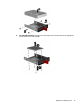
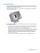
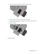
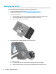
Table Of Contents
- Product features
- Hardware upgrades
- Warnings and cautions
- Preparing for disassembly
- Accessing the tool kit
- Replacing or installing drives
- Removing and replacing the access panel
- Installing system memory
- Installing graphics cards
- Removing the PCI fan
- Installing a system board
- Removing the hard drive fan
- Installing a power supply
- Installing a radiator bracket for liquid cooling
- Cleaning filters
- Electrostatic discharge
- Computer operating guidelines and routine care
- Accessibility
- Index
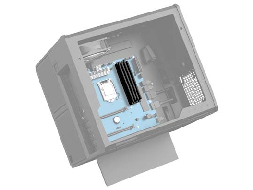
Populating DIMM sockets
There are four DIMM sockets on the system board, with two sockets per channel. The sockets are labeled
DIMM1, DIMM2, DIMM3, and DIMM4. The DIMM1 and DIMM3 sockets operate in memory channel A. The DIMM2
and DIMM4 sockets operate in memory channel B.
For improved performance, install memory modules in the following order: DIMM 4-2-3-1. Note that DIMM 1
is the slot closest to the processor.
The system will automatically operate in single-channel mode, dual-channel mode, or ex mode, depending
on how the DIMMs are installed.
●
The system will operate in single-channel mode if the DIMM sockets are populated in one channel only.
●
The system will operate in the higher-performing dual-channel mode if the memory capacity of the
DIMM in Channel A is equal to the memory capacity of the DIMM in Channel B.
●
The system will operate in ex mode if the memory capacity of the DIMM in Channel A is not equal to the
memory capacity of the DIMM in Channel B. In ex mode, the channel populated with the least amount
of memory describes the total amount of memory assigned to dual channel and the remainder is
assigned to single channel. If one channel will have more memory than the other, the larger amount
should be assigned to channel A.
●
In any mode, the maximum operational speed is determined by the slowest DIMM in the system.
Installing system memory 19