Hardware Reference Guide HP EliteDesk 705 G4 Desktop Mini
© Copyright 2018 HP Development Company, L.P. The information contained herein is subject to change without notice. The only warranties for HP products and services are set forth in the express warranty statements accompanying such products and services. Nothing herein should be construed as constituting an additional warranty. HP shall not be liable for technical or editorial errors or omissions contained herein.
About This Guide This guide provides basic information for upgrading the HP EliteDesk Business PC. WARNING! Indicates a hazardous situation that, if not avoided, could result in death or serious injury. CAUTION: Indicates a hazardous situation that, if not avoided, could result in minor or moderate injury. IMPORTANT: Indicates information considered important but not hazard-related (for example, messages related to property damage).
iv About This Guide
Table of contents 1 Product features ........................................................................................................................................... 1 Standard configuration features ........................................................................................................................... 1 Front panel components .......................................................................................................................................
Appendix B Computer operating guidelines, routine care and shipping preparation ............................................. 48 Computer operating guidelines and routine care ............................................................................................... 48 Shipping preparation ........................................................................................................................................... 49 Appendix C Accessibility ................................................
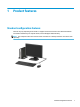
1 Product features Standard configuration features Features may vary depending on the model. For support assistance and to learn more about the hardware and software installed on your computer model, run the HP Support Assistant utility. NOTE: This computer model can be used in a tower orientation or a desktop orientation. The stand is sold separately.
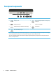
Front panel components Front panel components 1 USB Type-C port 5 Audio-out (headphone)/Audio-in (microphone) combo jack 2 USB SuperSpeed port 6 Hard drive activity light 3 USB SuperSpeed port with HP Sleep and Charge 7 Power button 4 Audio-out (headphone) jack NOTE: The USB SuperSpeed port with HP Sleep and Charge provides current to charge a device such as a smart phone. The charging current is available whenever the power cord is connected to the system, even when the system is off.
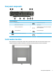
Rear panel components Rear panel components 1 Antenna cover 6 USB SuperSpeed ports (2) 2 External antenna locations 7 Optional port 3 Access panel thumbscrew 8 USB SuperSpeed ports with optional keyboard power-on support (2) 4 Security cable slot 9 RJ-45 (network) jack 5 DisplayPort monitor connectors (2) 10 Power connector Serial number location Each computer has a unique serial number and a product ID number that are located on the exterior of the computer.
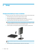
2 Setup Changing from desktop to tower orientation The computer can be used in a tower orientation with an optional tower stand that can be purchased from HP. 1. Remove/disengage any security devices that prohibit opening the computer. 2. Remove all removable media, such as a USB flash drive, from the computer. 3. Turn off the computer properly through the operating system, and turn off any external devices. 4. Disconnect the power cord from the AC outlet and disconnect any external devices.
NOTE: Ensure that at least 10.2 centimeters (4 inches) of space on all sides of the computer remains clear and free of obstructions. 7. Lock any security devices that were disengaged before the computer was moved. Attaching the computer to a mounting fixture The computer can be attached to a wall, swing arm, or other mounting fixture. NOTE: This apparatus is intended to be supported by UL or CSA Listed wall mount bracket. 1.
Installing a security lock You can attach a security cable lock to the rear of the computer. Use the key provided to attach and remove the lock. To install a padlock, slide the padlock loop out from the rear of the computer and install the padlock in the loop. NOTE: The cable lock and padlock are designed to act as a deterrent, but they may not prevent the computer from being mishandled or stolen.
Connecting the power cord Connect one end of the power cord to the AC adapter (1) and the other end to a grounded AC outlet (2), and then connect the round end of the AC adapter to the power connector on the computer (3).
3 Hardware upgrades Serviceability features The computer includes features that make it easy to upgrade and service. A Torx T15 or flat-bladed screwdriver is needed for some of the installation procedures described in this chapter. Warnings and cautions Before performing upgrades be sure to carefully read all of the applicable instructions, cautions, and warnings in this guide.
Removing the computer access panel To access internal components, you must remove the access panel. 1. Remove/disengage any security devices that prohibit opening the computer. 2. Remove all removable media, such as a USB flash drive, from the computer. 3. Turn off the computer properly through the operating system, and turn off any external devices. 4. Disconnect the power cord from the AC outlet and disconnect any external devices.
Replacing the computer access panel Place the access panel on the computer (1), and then slide it back (2). Then install the thumbscrew (3) to secure the panel in place. NOTE: Your computer model may look slightly different from the illustration in this section. Some models have vent holes on the access panel.
Upgrading system memory The computer comes with at least one small outline, dual in-line memory module (SODIMM). To achieve maximum memory support, you can populate the system board with up to 32 GB of memory. Memory module specifications For proper system operation, the memory modules must meet the following qualifications: Component Specification Memory modules 1.
Installing memory modules There are two memory module slots on the system board, with one slot per channel. The slots are labeled DIMM1 and DIMM3. The DIMM1 slot operates in memory channel B. The DIMM3 slot operates in memory channel A.
IMPORTANT: You must disconnect the power cord and wait approximately 30 seconds for the power to drain before adding or removing memory modules. Regardless of the power-on state, voltage is always supplied to the memory modules as long as the computer is plugged into an active AC outlet. Adding or removing memory modules while voltage is present may cause irreparable damage to the memory modules or system board. The memory module slots have gold-plated metal contacts.
14 8. Locate the memory module locations (1) and (2) on the system board. 9. To remove a memory module, press outward on the two latches on each side of the memory module (1), and then pull the memory module (2) out of the slot.
10. To install a memory module, match the notch on the new memory module with the tab on the memory slot (1). Slide the memory module into the slot (2) at approximately a 30° angle, and then press the memory module down (3) so that the latches lock it in place. NOTE: A memory module can be installed in only one way. Be sure to match the notch on the module with the tab on the memory module slot. 11. Tilt the fan down. 12. Replace the access panel.
13. If the computer was on a stand, replace the stand. 14. Reconnect the power cord and any external devices, and then turn on the computer. 15. Lock any security devices that were disengaged when the computer cover or access panel was removed. The computer should automatically recognize the new memory when you turn on the computer. Removing a hard drive NOTE: Before you remove the old hard drive, be sure to back up the data from the old hard drive so that you can transfer the data to the new hard drive.
Installing a hard drive NOTE: 1. See Removing a hard drive on page 16 for instructions on removing a hard drive. If you are replacing a hard drive, transfer the four mounting screws from the old hard drive to the new hard drive. NOTE: Mounting screws can be purchased from HP. 2. If you are installing a hard drive rather than replacing a hard drive, you must install the hard drive cage. Place the hard drive cage down into the chassis, and then slide it forward (1).
3. Align the hard drive mounting screws with the slots on the hard drive cage, press the hard drive down into the cage, and slide it forward (1). Then rotate the hard drive latch down (2) to engage the hard drive. 4. Replace the access panel. For instructions, see Replacing the computer access panel on page 10. 5. If the computer was on a stand, replace the stand. 6. Reconnect external devices, plug in the power cord, and then turn on the computer. 7.
a. Rotate the hard drive latch up (1) to disengage the hard drive from the cage. Then slide the drive toward the rear of the chassis until it stops, and then lift the hard drive up and out of the cage (2). b. Remove the hard drive cable clamp from the connector on the system board (1). Disconnect the hard drive cable (2) from the system board using the pull tab on the cable, and then remove the two screws (3) that secure the hard drive cage to the chassis.
b. 20 Remove the three screws (1) that secure the graphics processor to the chassis, and then lift the graphics processor (2) out of the chassis.
8. Locate the M.2 SSD on the system board. 9. Remove the screw (1) securing the SSD to the system board, and then pull the SSD from the socket (2) on the system board. Replacing an M.
10. Slide the connector end of the SSD into the socket (1) on the system board, and then secure the SSD with the screw (2). 11. Replace the hard drive cage or the graphics processor, depending on your model. For models with a hard drive: a. 22 Place the hard drive cage down into the chassis, and then slide it forward (1). Install the two screws (2) that secure the hard drive cage to the chassis, and then connect the hard drive cable (3) to the system board.
b. Align the hard drive mounting screws with the slots on the hard drive cage, press the hard drive down into the cage, and slide it forward (1). Then rotate the hard drive latch down (2) to engage the hard drive. For models with a graphics processor: a. Place the graphics processor down into the chassis so that it connects with the system board (1), and then secure the graphics processor to the system board with the three screws (2). Replacing an M.
b. Place the fan assembly (1) on the graphics processor. Secure the fan assembly with the four screws (2), and then connect the fan assembly cable (3) to the system board. 12. Replace the access panel. For instructions, see Replacing the computer access panel on page 10. 13. If the computer was on a stand, replace the stand. 14. Reconnect external devices, plug in the power cord, and then turn on the computer. 15.
Replacing the WLAN module 1. Remove/disengage any security devices that prohibit opening the computer. 2. Remove all removable media, such as a USB flash drive, from the computer. 3. Turn off the computer properly through the operating system, and turn off any external devices. 4. Disconnect the power cord from the AC outlet and disconnect any external devices.
b. Remove the hard drive cable clamp from the connector on the system board (1). Disconnect the hard drive cable (2) from the system board using the pull tab on the cable, and then remove the two screws (3) that secure the hard drive cage to the chassis. Slide the hard drive cage back and lift it (4) out of the chassis. For models with a graphics processor: a. 26 Disconnect the fan cable (1) from the system board.
b. 8. Remove the three screws (1) that secure the graphics processor to the chassis, and then lift the graphics processor (2) out of the chassis. Locate the WLAN module on the system board.
9. Disconnect both antenna cables (1) from the WLAN module. Remove the screw (2) securing the WLAN module to the system board, and then grasp the WLAN module by the sides and pull it out of the socket (3). NOTE: You may need to use a small tool, such as a pair of tweezers or needle-nose pliers, to disconnect and connect the antenna cables.
10. Insert the new WLAN module firmly into the socket (1) on the system board, and then secure the module to the system board using the screw (2) provided. Match the label on each antenna cable to the corresponding connector on the WLAN module and attach the antenna cables (3) to the connectors. NOTE: A WLAN module can be installed in only one way. 11. Replace the hard drive cage or the graphics processor, depending on your model. For models with a hard drive: a.
b. Align the hard drive mounting screws with the slots on the hard drive cage, press the hard drive down into the cage, and slide it forward (1). Then rotate the hard drive latch down (2) to engage the hard drive. For models with a graphics processor: a. 30 Place the graphics processor down into the chassis so that it connects with the system board (1), and then secure the graphics processor to the system board with the three screws (2).
b. Place the fan assembly (1) on the graphics processor. Secure the fan assembly with the four screws (2), and then connect the fan assembly cable (3) to the system board. 12. Replace the access panel. For instructions, see Replacing the computer access panel on page 10. 13. If the computer was on a stand, replace the stand. 14. Plug in the power cord and turn on the computer. 15. Lock any security devices that were disengaged when the computer cover or access panel was removed.
Installing an external antenna Internal WLAN antennas are standard. If the computer is to be installed in a metal kiosk or other enclosure, you may want to use an external WLAN antenna. 1. Remove/disengage any security devices that prohibit opening the computer. 2. Remove all removable media, such as a USB flash drive, from the computer. 3. Turn off the computer properly through the operating system, and turn off any external devices. 4.
b. Remove the hard drive cable clamp from the connector on the system board (1). Disconnect the hard drive cable (2) from the system board using the pull tab on the cable, and then remove the two screws (3) that secure the hard drive cage to the chassis. Slide the hard drive cage back and lift it (4) out of the chassis. For models with a graphics processor: a. Disconnect the fan cable (1) from the system board.
b. Remove the three screws (1) that secure the graphics processor to the chassis, and then lift the graphics processor (2) out of the chassis. 8. Locate the WLAN module on the system board. 9. Disconnect the internal antenna cables from the WLAN module. For instructions, see Replacing the WLAN module on page 25. 10. Locate both external antenna positions on the rear of the chassis.
11. To view the knock-out feature on the left side of the rear panel, remove the antenna cover by pushing down on the antenna cover (1) and pulling it away from the panel (2). Disconnect the internal antenna (3) from the chassis and pull the internal antenna cable out of the chassis. Then insert a flat-bladed screwdriver into each knock-out feature (3) and rotate to remove the blanks. NOTE: You may need needle nose pliers to pull the internal cable out of the chassis. 12.
a. Place the hard drive cage down into the chassis, and then slide it forward (1). Install the two screws (2) that secure the hard drive cage to the chassis, and then connect the hard drive cable (3) to the system board. Secure the cable by attaching the hard drive cable clamp (4) to the system board connector. b. Align the hard drive mounting screws with the slots on the hard drive cage, press the hard drive down into the cage, and slide it forward (1).
b. Place the fan assembly (1) on the graphics processor. Secure the fan assembly with the four screws (2), and then connect the fan assembly cable (3) to the system board. 15. Replace the access panel. For instructions, see Replacing the computer access panel on page 10. 16. If the computer was on a stand, replace the stand. 17. Plug in the power cord and turn on the computer. 18. Lock any security devices that were disengaged when the computer cover or access panel was removed.
Replacing the battery The battery that comes with the computer provides power to the real-time clock. When replacing the battery, use a battery equivalent to the battery originally installed in the computer. The computer comes with a 3-volt lithium coin cell battery. WARNING! The computer contains an internal lithium manganese dioxide battery. There is a risk of fire and burns if the battery is not handled properly. To reduce the risk of personal injury: Do not attempt to recharge the battery.
b. Remove the hard drive cable clamp from the connector on the system board (1). Disconnect the hard drive cable (2) from the system board using the pull tab on the cable, and then remove the two screws (3) that secure the hard drive cage to the chassis. Slide the hard drive cage back and lift it (4) out of the chassis. For models with a graphics processor: a. Disconnect the fan cable (1) from the system board.
b. 40 Remove the three screws (1) that secure the graphics processor to the chassis, and then lift the graphics processor (2) out of the chassis.
8. Locate the battery and battery holder on the system board. NOTE: You may need to use a small tool, such as tweezers or needle-nose pliers, to remove and replace the battery. 9. Lift the battery out of the holder. 10. Slide the replacement battery into position, positive side up. The battery holder automatically secures the battery in the proper position. 11. Replace the hard drive cage or the graphics processor, depending on your model. For models with a hard drive: a.
b. Align the hard drive mounting screws with the slots on the hard drive cage, press the hard drive down into the cage, and slide it forward (1). Then rotate the hard drive latch down (2) to engage the hard drive. For models with a graphics processor: a. 42 Place the graphics processor down into the chassis so that it connects with the system board (1), and then secure the graphics processor to the system board with the three screws (2).
b. Place the fan assembly (1) on the graphics processor. Secure the fan assembly with the four screws (2), and then connect the fan assembly cable (3) to the system board. 12. Replace the computer access panel. 13. If the computer was on a stand, replace the stand. 14. Plug in the power cord and turn on the computer. 15. Lock any security devices that were disengaged when the computer access panel was removed. 16. Reset the date and time, your passwords, and any special system setups using Computer Setup.
Synchronizing the optional wireless keyboard and mouse The mouse and keyboard are synchronized at the factory. If they do not work, remove and replace the batteries. If the mouse and keyboard are still not synchronized, follow this procedure to manually resynchronize the pair. 44 1. Connect the receiver to a USB port on the computer. If your computer only has USB SuperSpeed ports, connect the receiver to a USB SuperSpeed port. 2.
3. Press the Connect button on the receiver for approximately five seconds. The status light on the receiver will flash for approximately 30 seconds after the Connect button is pressed. 4. While the status light on the receiver is flashing, press the Connect button on the underside of the keyboard for five to ten seconds. After the Connect button is released, the status light on the receiver will stop flashing, indicating that the devices have been synchronized.
5. Press the Connect button on the receiver for approximately five seconds. The status light on the receiver will flash for approximately 30 seconds after the Connect button is pressed. 6. While the status light on the receiver is flashing, press the Connect button on the underside of the mouse for five to ten seconds. After the Connect button is released, the status light on the receiver will stop flashing, indicating that the devices have been synchronized.
A Electrostatic discharge A discharge of static electricity from a finger or other conductor may damage system boards or other staticsensitive devices. This type of damage may reduce the life expectancy of the device. Preventing electrostatic damage To prevent electrostatic damage, observe the following precautions: ● Avoid hand contact by transporting and storing products in static-safe containers. ● Keep electrostatic-sensitive parts in their containers until they arrive at static-free workstations.
B Computer operating guidelines, routine care and shipping preparation Computer operating guidelines and routine care Follow these guidelines to properly set up and care for the computer and monitor: 48 ● Keep the computer away from excessive moisture, direct sunlight, and extremes of heat and cold. ● Operate the computer on a sturdy, level surface. Leave a 10.2 cm (4 inch) clearance on all vented sides of the computer and above the monitor to permit the required airflow.
Shipping preparation Follow these suggestions when preparing to ship the computer: 1. Back up the hard drive files to an external storage device. Be sure that the backup media is not exposed to electrical or magnetic impulses while stored or in transit. NOTE: The hard drive locks automatically when the system power is turned off. 2. Remove and store all removable media. 3. Turn off the computer and external devices. 4. Disconnect the power cord from the AC outlet, then from the computer. 5.
C Accessibility HP designs, produces, and markets products and services that can be used by everyone, including people with disabilities, either on a stand-alone basis or with appropriate assistive devices. Supported assistive technologies HP products support a wide variety of operating system assistive technologies and can be configured to work with additional assistive technologies. Use the Search feature on your device to locate more information about assistive features.
Index A access panel removal 9 replacement 10 accessibility 50 B battery installation 38 removal 38 C computer operating guidelines 48 E electrostatic discharge, preventing damage 47 external antenna installation 32 F front components 2 H hard drive installation 17 removal 16 I installation guidelines 8 installing battery 38 computer access panel 10 external antenna 32 hard drive 17 memory modules 11, 12 security lock 6 solid state drive 18 WLAN module 25 K keyboard synchronizing wireless 44 synchroniz