HP ProBook 4230s Notebook PC Maintenance and Service Guide
© Copyright 2011 Hewlett-Packard Development Company, L.P. Bluetooth is a trademark owned by its proprietor and used by Hewlett-Packard Company under license. Intel and Core are trademarks or registered trademarks of Intel Corporation in the United States and other countries. Microsoft, Windows, and Windows Vista are either trademarks or registered trademarks of Microsoft Corporation in the United States and/or other countries. SD Logo is a trademark of its proprietor.
Safety warning notice WARNING! To reduce the possibility of heat-related injuries or of overheating the computer, do not place the computer directly on your lap or obstruct the computer air vents. Use the computer only on a hard, flat surface. Do not allow another hard surface, such as an adjoining optional printer, or a soft surface, such as pillows or rugs or clothing, to block airflow.
iv Safety warning notice
Table of contents 1 Product description ........................................................................................................................................ 1 2 External component identification ................................................................................................................ 7 Display .................................................................................................................................................. 7 Top ....................
Grounding guidelines ......................................................................................................... 36 Electrostatic discharge damage ........................................................................ 36 Packaging and transporting guidelines ............................................. 37 Workstation guidelines ..................................................................... 37 Equipment guidelines .......................................................................
30.7-cm (12.1-in), HD+ display specifications .................................................................................... 84 Hard drive specifications .................................................................................................................... 85 Specification information in Device Manager ..................................................................................... 86 7 Backup and recovery .............................................................................
viii
1 Product description Category Description Product Name HP ProBook 4230s Notebook PC Processors Intel® Core™ i7 processor, Dual Core 2620M, 2.70-GHz (Turbo up to 3.40-MHz) processor 4-MB L3 cache, 4 threads Intel Core i5 processors, Dual Core 2540M, 2.60-GHz (Turbo up to 3.30-MHz) processor 3-MB L3 cache, 4 threads 2520M, 2.50-GHz (Turbo up to 3.20-MHz) processor 3-MB L3 cache, 4 threads 2430M, 2.40-GHz (Turbo up to 3.0-MHz) processor 3-MB L3 cache, 4 threads 2410M, 2.30-GHz (Turbo up to 2.
Category Description 30.7-cm (12.1-inch) WXGA, 1280x800 with camera and WWAN, anti-glare 30.7-cm (12.1-inch) WXGA, 1280x800, BrightView 30.7-cm (12.
Category Description Modem cable not included Supports “No Modem” option Ethernet Realtek RTL8151EH-CG 10/100/1000 S3/S4/S5 wake on LAN Ethernet cable not included Wireless Integrated WLAN options by way of wireless module: Two WLAN antennas built into display assembly Supports “no WLAN” option Supports the following WLAN formats: ● Ralink 802.11 b/g/n 1×1 ● Realtek 802.11 b/g/n 1×1 ● Atheros 802.11 b/g/n +BT Combo ● Ralink 802.11 a/b/g/n +BT Combo ● Realtek 802.
Category Description Keyboard/pointing devices Full-sized keyboard Touchpad includes: supports 2-way scroll with legend, taps enabled by default, 2finger scrolling and zoom enabled by default Power requirements Smart AC adapter with localized cable plug support (3-wire plug with ground pin): 65-W “Smart” AC adapter 65-W “Slim” AC adapter (ABJ and ACF only) In-line cavity 6-cell, 62-Wh Li-ion battery 4-cell, 41-Wh Li-ion battery Security Integrated fingerprint reader Intel AT support Support Kensingto
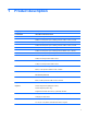
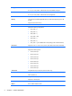
Category Description Windows 7 Home Premium 32 with Microsoft Office 2010 Personal Windows 7 Home Premium 32 with Microsoft Office 2010 Home & Business Windows 7 Home Premium 32 with Microsoft Office 2010 Professional Windows 7 Home Premium 64 with Microsoft Office 2010 Starter EDGI Windows 7 Home Premium 64 with Microsoft Office 2010 Starter Windows 7 Premium 64 with Microsoft Office 2010 Personal Windows 7 Premium 64 with Microsoft Office 2010 Home & Business Windows 7 Premium 64 with Microsoft Office 20
Category Description WLAN module WWAN module, SIM Keyboard 6 Chapter 1 Product description
2 External component identification Display Component Description (1) WWAN antennas (2)* (select models only) Send and receive wireless signals to communicate with wireless wide-area networks (WWAN). (2) WLAN antennas (2)* Send and receive wireless signals to communicate with wireless local area networks (WLAN). (3) Internal microphone(s) (1 or 2 depending on model) Record sound. (4) Webcam light (select models only) On: The webcam is in use.
Component Description (5) Records video and captures still photographs. Webcam (select models only) To use the webcam, select Start > All Programs > ArcSoft Camera Suite > WebCam Companion. *The antennas are not visible from the outside of the computer. For optimal transmission, keep the areas immediately around the antennas free from obstructions. To see wireless regulatory notices, refer to the section of the Regulatory, Safety, and Environmental Notices that applies to your country or region.
Lights Component (1) (2) Description Power light QuickWeb light ● On: The computer is on. ● Blinking: The computer is in the Sleep state. ● Off: The computer is off or in Hibernation. ● On: The computer is on or the default Web browser is in use. ● Blinking: When the QuickWeb button is pressed, the light blinks 5 times, and then the default Web browser opens. NOTE: To use HP QuickWeb when the computer is off, HP QuickWeb must be enabled in Computer Setup.
Buttons and fingerprint reader (select models only) Component (1) Description Power button ● When the computer is off, press the button to turn on the computer. ● When the computer is on, press the button briefly to initiate Sleep. ● When the computer is in the Sleep state, press the button briefly to exit Sleep. ● When the computer is in Hibernation, press the button briefly to exit Hibernation.
Component (2) Description HP QuickWeb light ● When the computer is off or in Hibernation, press the button to open HP QuickWeb. ● When the computer is in Microsoft Windows, press the button to open the default Web browser. ● When the computer is in HP QuickWeb, press the button to open the default Web browser. NOTE: For more information, refer to “HP QuickWeb” in this guide and to the HP QuickWeb software Help.
Keys Component 12 Description (1) esc key Displays system information when pressed in combination with the fn key. (2) fn key Executes frequently used system functions when pressed in combination with a function key, the num lk key, or the esc key. (3) Start key Displays the Start menu. (4) Function keys Execute frequently used system functions when pressed in combination with the fn key. (5) Menu key Displays the active programs's shortcut menu (same as the right-click menu).
Front Component Description (1) ● Blinking white: The hard drive is being accessed. ● Amber: HP 3D DriveGuard has temporarily parked the hard drive. (2) Drive light Media Card Reader Supports the following digital card formats: ● Memory Stick Pro ● Memory Stick Duo Pro ● MultiMediaCard ● MultiMediaCard Micro ● Secure Digital (SD) Card ● Secure Digital (SD) Card Micro (3) Speakers (2) Produce sound.
Left Component (1) Description Security cable slot Attaches an optional security cable to the computer. NOTE: The security cable is designed to act as a deterrent, but it may not prevent the computer from being mishandled or stolen. (2) RJ-11 (modem) jack (select models only) Connects a modem cable. (3) Vent Enables airflow to cool internal components. NOTE: The computer fan starts up automatically to cool internal components and prevent overheating.
Right Component (1) Description AC adapter light ● White: The computer is connected to external power and the battery is 90 to 99% charged. ● Amber: The computer is connected to external power and the battery is 0 to 90% charged. ● Blinking amber: A battery that is the only available power source has reached a low battery level. When the battery reaches a critical battery level, the battery light begins blinking rapidly. ● Off: The battery is fully charged.
Bottom Component Description (1) Battery and access cover release latches Release the battery from the battery bay, and release the access cover from the computer. (2) Battery bay Holds the battery. (3) SIM slot Contains a wireless subscriber identity module (SIM) (select models only). The SIM slot is located inside the battery bay. (4) Vents (2) Enable airflow to cool internal components. NOTE: The computer fan starts up automatically to cool internal components and prevent overheating.
3 Illustrated parts catalog Service tag When ordering parts or requesting information, provide the computer serial number and model description provided on the service tag. ● Product name (1). This is the product name affixed to the front of the computer. ● Serial number (s/n) (2). This is an alphanumeric identifier that is unique to each product. ● Part number/Product number (p/n) (3). This number provides specific information about the product's hardware components.
Computer major components Item Description (1) Display panel (2) Spare part number 30.7-cm (12.1-inch) WXGA, anti-glare 646017-001 30.7-cm (12.1-inch) WXGA, anti-glare with webcam 646019-001 30.7-cm (12.1-inch) WXGA, anti-glare with webcam and WWAN 646021-001 30.7-cm (12.1-inch) WXGA, BrightView 646023-001 30.7-cm (12.
Item Description Spare part number With a fingerprint reader slot insert for use in computers that do not support a fingerprint reader 657232-001 For use in computers with USB 2.0 and a fingerprint reader 657960-001 For use in computers with USB 2.0 and without a fingerprint reader 657961-001 With no USB logo for use in USB 2.0 or USB 3.0 computers with a fingerprint reader 666893-001 With no USB logo for use in USB 2.0 or USB 3.
Item Description Spare part number Intel Celeron processors (12) (13) B840, 1.9-GHz, with 2-MB L3 cache 664663-001 B810, 1.6-GHz, with 2-MB L3 cache 646760-001 WWAN modules HP un2430 EV-DO/HSPA Mobile Broadband Module 634400-001 HP hs2340 HSPA+ Mobile Broadband Module 632155-001 WLAN modules Atheros AR9002WB-1NGB 802.11b/g/n 1x1 WiFi and Bluetooth 2.
Item Description Spare part number Realtek 8188BC8 802.11a/b/g/n 2x2 WiFi and Bluetooth 3.
Item 22 Description Spare part number Ralink 8190BC8 802.11b/g/n 2x2 WiFi and Bluetooth 3.
Item (14) Description Spare part number Intel Centrino® Advanced-N 6230 for use in Afghanistan, Albania, Algeria, Andorra, Angola, Antigua and Barbuda, Argentina, Armenia, Aruba, Australia, Austria, Azerbaijan, Bahamas, Bahrain, Baltics, Bangladesh, Barbados, Belarus, Belgium, Belize, Benin, Bermuda, Bhutan, Bolivia, Bosnia and Herzegovina, Botswana, Brazil, the British Virgin Islands, Brunei, Bulgaria, Burkina Faso, Burundi, Cambodia, Cameroon, Canada, Cape Verde, the Cayman Islands, Central African Re
Item Description Spare part number 6-cell, 55 WHr, 2.8 Ah Li-ion battery 660151-001 4-cell (41 WHr, 2.
Item Description Spare part number (8) Display enclosure 646012-001 Bracket Kit (includes RJ-11 bracket and power bracket; not illustrated) 646045-001 Plastics Kit Item Description Spare part number Plastics Kit 646035-001 (1) RJ-11 holder (2) Secure Digital card protective insert (3) SIM protective insert Plastics Kit 25
Cable Kit Item Description Spare part number Cable Kit 646016-001 (1) Hard drive cable (2) RJ-11 connector cable Mass storage devices Description Spare part number Hard drives 26 750-GB, 7200-rpm 633252-001 640-GB, 5400-rpm 603785-001 500-GB, 7200-rpm 634926-001 500-GB, 5400-rpm 634638-001 320-GB, 5400-rpm 645193-001 320-GB, 7200-rpm 634862-001 250-GB, 7200-rpm 634861-001 250-GB, 5400-rpm 645191-001 Hard Drive Hardware Kit (includes hard drive bracket, insulator, and screws) 6
Miscellaneous parts Description Spare part number AC adapters 65-W AC adapter 609939-001 65-W AC adapter for use in India 609948-001 65-W travel adapter 592814-001 Power cords: For use in Australia and New Zealand 490371-011 For use in the People's Republic of China 490371-AA1 For use in Europe, the Middle East, and Africa 490371-021 For use in India 490371-D61 For use in South Korea 490371-AD1 For use in Taiwan 490371-AB1 For use in the United Kingdom 490371-031 For use in the United
Sequential part number listing 28 Spare part number Description 390632-001 Mouse, optical, 2-button 414135-001 Power cable, 65-W 434594-001 HP optical travel mouse 455084-001 HP basic carrying case 490371-001 Power cord for use in North America 490371-011 Power cord for use in Australia and New Zealand 490371-021 Power cord for use in Europe, the Middle East, and Africa 490371-031 Power cord for use in the United Kingdom 490371-291 Power cord for use in Japan 490371-AA1 Power cord for
Spare part number Description 602993-001 Realtek 8188BC8 802.11a/b/g/n 2x2 WiFi and Bluetooth 3.
30 Spare part number Description 630703-001 Ralink 5390GN 802.
Spare part number Description 633803-001 6-cell, 62 WHr, 2.
32 Spare part number Description 640926-001 Realtek 8188GN 802.
Spare part number Description 646029-AB1 Keyboard for use in Taiwan 646029-AD1 Keyboard for use in South Korea 646029-D61 Keyboard for use in India 646035-001 Plastics Kit 646036-001 Rubber Kit (includes bottom feet) 646037-001 Screw Kit 646038-001 Speaker Kit 646039-001 System board for use in models without WWAN 646040-001 System board for models with WWAN 646040-AA1 System board for use in models with WWAN in Russia and the People's Republic of China 646041-001 Top cover for use in
4 Removal and replacement procedures Preliminary replacement requirements Tools required You will need the following tools to complete the removal and replacement procedures: ● Flat-bladed screwdriver ● Phillips P0 and P1 screwdrivers ● Torx T8 screwdriver Service considerations The following sections include some of the considerations that you must keep in mind during disassembly and assembly procedures.
Cables and connectors CAUTION: When servicing the computer, be sure that cables are placed in their proper locations during the reassembly process. Improper cable placement can damage the computer. Cables must be handled with extreme care to avoid damage. Apply only the tension required to unseat or seat the cables during removal and insertion. Handle cables by the connector whenever possible. In all cases, avoid bending, twisting, or tearing cables.
Grounding guidelines Electrostatic discharge damage Electronic components are sensitive to electrostatic discharge (ESD). Circuitry design and structure determine the degree of sensitivity. Networks built into many integrated circuits provide some protection, but in many cases, ESD contains enough power to alter device parameters or melt silicon junctions. A discharge of static electricity from a finger or other conductor can destroy static-sensitive devices or microcircuitry.
Packaging and transporting guidelines Follow these grounding guidelines when packaging and transporting equipment: ● To avoid hand contact, transport products in static-safe tubes, bags, or boxes. ● Protect ESD-sensitive parts and assemblies with conductive or approved containers or packaging. ● Keep ESD-sensitive parts in their containers until the parts arrive at static-free workstations. ● Place items on a grounded surface before removing items from their containers.
Equipment guidelines Grounding equipment must include either a wrist strap or a foot strap at a grounded workstation. ● When seated, wear a wrist strap connected to a grounded system. Wrist straps are flexible straps with a minimum of one megohm ±10% resistance in the ground cords. To provide proper ground, wear a strap snugly against the skin at all times. On grounded mats with banana-plug connectors, use alligator clips to connect a wrist strap.
Component replacement procedures This chapter provides removal and replacement procedures. There are as many as 95 screws and screw locks, in 15 different sizes, that must be removed, replaced, or loosened when servicing the computer. Make special note of each screw and screw lock size and location during removal and replacement. Service tag When ordering parts or requesting information, provide the computer serial number and model description provided on the service tag. ● Product name (1).
Computer feet The computer feet are adhesive-backed rubber pads. The feet are included in the Rubber Kit, spare part number 646036-001. There are 4 rubber feet that attach to the base enclosure in the locations illustrated below.
Battery Description Spare part number 6-cell, 62 WHr, 2.8 Ah Li-ion battery 633803-001 6-cell, 55 WHr, 2.8 Ah Li-ion battery 660151-001 4-cell, 41 WHr, 2.8 Ah Li-ion battery 633801-001 Before disassembling the computer, follow these steps: 1. Shut down the computer. If you are unsure whether the computer is off or in Hibernation, turn the computer on, and then shut it down through the operating system. 2. Disconnect all external devices connected to the computer. 3.
SIM NOTE: This section applies only to computer models with WWAN capability. NOTE: If there is a SIM inserted in the SIM slot, it must be removed before disassembling the computer. Be sure that the SIM is reinserted in the SIM slot after reassembling the computer. Before removing the SIM, follow these steps: 1. Shut down the computer. If you are unsure whether the computer is off or in Hibernation, turn the computer on, and then shut it down through the operating system. 2.
Access door Description Spare part number Access door 646049-001 Before disassembling the computer, follow these steps: 1. Shut down the computer. If you are unsure whether the computer is off or in Hibernation, turn the computer on, and then shut it down through the operating system. 2. Disconnect all external devices connected to the computer. 3. Disconnect the power from the computer by first unplugging the power cord from the AC outlet, and then unplugging the AC adapter from the computer. 4.
Hard drive NOTE: All hard drive spare part kits include a hard drive bracket and screws.
5. Disconnect the hard drive cable from the hard drive (4). 6. If it is necessary to replace the hard drive bracket, remove the tape (1) that secures the Mylar cover down onto the bracket, and then lift to open the Mylar cover (2). 7. Remove the two Phillips PM3.0×3.0 hard drive bracket screws (3) from each side of the hard drive (4 total screws). 8. Rotate the hard drive upward and remove it from the bracket (4). Reverse this procedure to reassemble and install the hard drive.
Memory modules NOTE: This procedure is valid for either memory module. Description Spare part number 1-GB (PC3-10600, 1333-MHz, DDR3) 639736-001 2-GB (PC3-10600, 1333-MHz, DDR3) 621565-001 4-GB (PC3-10600, 1333-MHz, DDR3) 621569-001 Update BIOS before adding memory modules Before adding new memory, make sure you update the computer to the latest BIOS. CAUTION: Failure to update the computer to the latest BIOS prior to installing new memory may result in various system problems. To update BIOS: 1.
3. Remove the memory module (2) by pulling the module away from the slot at an angle. NOTE: Memory modules are designed with a notch (3) to prevent incorrect insertion into the memory module slot. Reverse this procedure to install a memory module. WWAN module CAUTION: The WWAN module and the WLAN module are not interchangeable.
Remove the WWAN module: 1. Position the computer upside-down with the battery bay toward you. 2. Disconnect the WWAN antenna cables (1) from the terminals on the WWAN module. NOTE: The red WWAN antenna cable is connected to the WWAN module “Main” terminal. The blue WWAN antenna cable is connected to the WWAN module “Aux” terminal. 3. Remove the two Phillips PM2.0×4.0 screws (2) that secure the WWAN module to the computer. (The edge of the module opposite the slot rises away from the computer.) 4.
WLAN/Bluetooth combo card The computer uses a card that provides both WLAN and Bluetooth functionality. CAUTION: The WLAN module and the WWAN module are not interchangeable. Description Spare part number Atheros AR9002WB-1NGB 802.11b/g/n 1x1 WiFi and Bluetooth 2.
50 Description Spare part number Ralink 5390GN 802.
Description Spare part number Realtek 8188GN 802.
3. Disconnect the power from the computer by first unplugging the power cord from the AC outlet, and then unplugging the AC adapter from the computer. 4. Remove the battery (see Battery on page 41). 5. Remove the access door (see Access door on page 43). Remove the WLAN module: 1. Position the computer upside-down with the battery bay toward you. 2. Disconnect the WLAN antenna cables (1) from the terminals on the WLAN module.
4. Remove the WLAN module (3) by pulling the module away from the slot at an angle. NOTE: WLAN modules are designed with a notch (4) to prevent incorrect insertion. NOTE: If the WLAN antennas are not connected to the terminals on the WLAN module, the protective sleeves must be installed on the antenna connectors, as shown in the following illustration. Reverse this procedure to install the WLAN module.
Keyboard NOTE: For a detailed list of available keyboards, see Sequential part number listing on page 28. Description Spare part number Keyboard 646029-xxx Before removing the keyboard, follow these steps: 1. Shut down the computer. If you are unsure whether the computer is off or in Hibernation, turn the computer on, and then shut it down through the operating system. 2. Disconnect all external devices connected to the computer. 3.
5. Position the computer upright and open it as far as possible. 6. Using a slim screwdriver, release the four top keyboard tabs at the indicated locations and lift the top of the keyboard up and place it on the palm rest. 7. Lift the keyboard connector latch and disconnect the keyboard cable from the system board. 8. Remove the keyboard from the computer. Reverse this procedure to install the keyboard. Top cover Description Spare part number Top cover for use in models with USB 3.
Before removing the top cover, follow these steps: 1. Shut down the computer. If you are unsure whether the computer is off or in Hibernation, turn the computer on, and then shut it down through the operating system. 2. Disconnect all external devices connected to the computer. 3. Disconnect the power from the computer by first unplugging the power cord from the AC outlet, and then unplugging the AC adapter from the computer. 4. Remove the battery (see Battery on page 41). 5.
5. Remove the following cables from the system board: (3) Power button (4) QuickLaunch board (5) Card reader (6) Touchpad 6. Position the upside-down with the battery bay toward you. 7. Insert a screwdriver through the holes in the battery bay and press to disengage the top cover from the computer. 8. Position the computer upright with the front toward you.
9. To remove the top cover, lift the top and pull the cover away from the display until it clears the front audio ports, and then lift it off the computer. Reverse this procedure to install the top cover.
Quick Launch board Description Spare part number Quick Launch board 646048-001 Before removing the Quick Launch board, follow these steps: 1. Shut down the computer. If you are unsure whether the computer is off or in Hibernation, turn the computer on, and then shut it down through the operating system. 2. Disconnect all external devices connected to the computer. 3.
Power button board Description Spare part number Power button board 647132-001 Before removing the power button board, follow these steps: 1. Shut down the computer. If you are unsure whether the computer is off or in Hibernation, turn the computer on, and then shut it down through the operating system. 2. Disconnect all external devices connected to the computer. 3.
Modem module NOTE: The modem module spare part kit does not include a modem module cable. The modem module cable is included in the Cable Kit, spare part number 646016-001. See Cable Kit on page 26 for more Cable Kit spare part number information. Description Spare part number Modem module 628824-001 Before removing the modem module, follow these steps: 1. Shut down the computer.
4. Disconnect the modem module cable (3) from the modem module. Reverse this procedure to install the modem module. Speaker assembly Description Spare part number Speaker Kit 646038-001 Before removing the speaker assembly, follow these steps: 62 1. Shut down the computer. If you are unsure whether the computer is off or in Hibernation, turn the computer on, and then shut it down through the operating system. 2. Disconnect all external devices connected to the computer. 3.
Remove the speaker assembly: 1. Position the computer upright with the front toward you. 2. Disconnect the cable from the system board (1). 3. Remove the tape the secures the speaker cable to the system board (2). 4. Lift the speaker from the computer (3). Reverse this procedure to install the speaker assembly. System board NOTE: All system board spare part kits include replacement thermal material.
4. Remove the battery (see Battery on page 41). 5. Remove the following components: a. Access door (see Access door on page 43). b. Hard drive (see Hard drive on page 44) c. Keyboard (see Keyboard on page 54) d. Top cover (see Top cover on page 55) e.
6. Lift the right side of the system board up at an angle (5), and then lift the system board from the computer (6). Reverse this procedure to install the system board. RTC battery Description Spare part number RTC battery 650924-001 Before removing the RTC battery, follow these steps: 1. Shut down the computer. If you are unsure whether the computer is off or in Hibernation, turn the computer on, and then shut it down through the operating system. 2.
Remove the RTC battery: 1. Position the system board upside-down. 2. Use a screwdriver to loosen the battery from the slot (1). 3. Lift the battery from the system board (2). Reverse this procedure to install the RTC battery.
Fan Description Spare part number Fan 646027-001 Before removing the fan, follow these steps: 1. Shut down the computer. If you are unsure whether the computer is off or in Hibernation, turn the computer on, and then shut it down through the operating system. 2. Disconnect all external devices connected to the computer. 3. Disconnect the power from the computer by first unplugging the power cord from the AC outlet, and then unplugging the AC adapter from the computer. 4.
4. Remove the fan from the system board (3). Reverse this procedure to install the fan. NOTE: To properly ventilate the computer, allow at least a 7.6-cm (3-in) clearance on the left side of the computer. The computer uses an electric fan for ventilation. The fan is controlled by a temperature sensor and is designed to turn on automatically when high temperature conditions exist.
Heat sink All heat sink spare part kits include replacement thermal material. Description Spare part number Heat sink 646028-001 Before removing the heat sink, follow these steps: 1. Shut down the computer. If you are unsure whether the computer is off or in Hibernation, turn the computer on, and then shut it down through the operating system. 2. Disconnect all external devices connected to the computer. 3.
3. Remove the heat sink from the system board (5). NOTE: Thoroughly clean thermal material from the surfaces of the system board component (1) and the heat sink (2) each time you remove the heat sink. All heat sink and processor spare part kits include thermal material. Reverse this procedure to install the heat sink.
Processor NOTE: All processor spare part kits include replacement thermal material. Description Spare part number Intel Core i7 processor, Dual Core 2620M, 2.7-GHz (turbo up to 3.4-GHz) processor with 4-MB L3 cache (includes thermal grease) 631252-001 Intel Core i5 processors, Dual Core 2540M, 2.6-GHz (turbo up to 3.3-GHz) processor with 3-MB L3 cache (includes thermal grease) 631255-001 2520M, 2.5-GHz (turbo up to 3.
f. Modem module (see Modem module on page 61) g. System board (see System board on page 63) h. Fan (see Fan on page 67) i. Heat sink (see Heat sink on page 69). Remove the processor: 1. Position the system board upside-down. 2. Use a flat-bladed screwdriver to turn the processor locking screw (1) one-half turn counterclockwise until you hear a click. 3. Lift the processor (2) straight up and remove it.
RJ-11 jack cable NOTE: The RJ-11 jack cable is included in the Cable Kit, spare part number 646016-001. The RJ-11 bracket is available in the Bracket Kit, spare part number 646045-001. Before removing the RJ-11 jack cable, follow these steps: 1. Shut down the computer. If you are unsure whether the computer is off or in Hibernation, turn the computer on, and then shut it down through the operating system. 2. Disconnect all external devices connected to the computer. 3.
Reverse this procedure to install the RJ-11 jack cable. Display assembly All display assemblies include WLAN antenna transceivers and cables. WWAN models include 2 WWAN antenna transceivers and cables. Description Spare part number Display assembly, 30.7-cm (12.1-inch) WXGA, anti-glare 646017-001 Display assembly, 30.7-cm (12.1-inch) WXGA, anti-glare with webcam 646019-001 Display assembly, 30.7-cm (12.1-inch) WXGA, anti-glare with webcam and WWAN 646021-001 Display assembly, 30.7-cm (12.
4. Remove the five Phillips PM2.5×8.0 screws (2) from the hinges, the Phillips PM2.5×8.0 screw (3) from the security bracket, and then lift the display from the computer (4). When installing the display assembly, be sure that the wireless antenna cables are routed and arranged properly. Failure to properly route the antennas can result in degradation of the computer's WLAN and WWAN performance. 5. To replace the display bezel, remove the two rubber screw covers and the two Phillips PM2.5×5.
9. If it is necessary to replace the webcam module (shown in the following image) or microphone module from the display enclosure, disconnect the cable from the module (1), and then gently pull the module away from the double-sided tape on the display enclosure (2). The webcam module is available using spare part number 642795-001. The microphone module is removed using the same procedure and is available using spare part number 642797-001. 10.
12. Disconnect the display panel cable from the back of the display panel by pressing the latches on the side of the connector (1), and then disconnecting the cable from the panel (2). The display cable is available using spare part number 646044-001, and includes the integrated webcam cable. 13. If it is necessary to replace the display hinges, remove the two Phillips PM2.5×3.0 screws that secure each display hinge to the display panel, and then remove the hinges from the panel.
14. If you need to remove the WLAN or WWAN antennas, lift the WLAN antenna cables (1) or WWAN antenna cables (2) from the clips and routing paths built into the display enclosure. The WLAN antennas are available using spare part number 646010-001, and the WWAN antennas are available using spare part number 646011-001. CAUTION: When installing the display assembly, be sure that the wireless antenna cables are routed and arranged properly.
5 Computer Setup (BIOS) and System Diagnostics Using Computer Setup Computer Setup, or Basic Input/Output System (BIOS), controls communication between all the input and output devices on the system (such as disk drives, display, keyboard, mouse, and printer). Computer Setup includes settings for the types of devices installed, the startup sequence of the computer, and the amount of system and extended memory. NOTE: Use extreme care when making changes in Computer Setup.
To exit Computer Setup menus, choose one of the following methods: ● To exit Computer Setup menus without saving your changes: Click the Exit icon in the lower-left corner of the screen, and then follow the on-screen instructions. – or – Use the tab key and the arrow keys to select File > Ignore Changes and Exit, and then press enter. ● To save your changes and exit Computer Setup menus: Cclick the Save icon in the lower-left corner of the screen, and then follow the on-screen instructions.
Updating the BIOS Updated versions of the BIOS may be available on the HP Web site. Most BIOS updates on the HP Web site are packaged in compressed files called SoftPaqs. Some download packages contain a file named Readme.txt, which contains information regarding installing and troubleshooting the file.
NOTE: If you connect your computer to a network, consult the network administrator before installing any software updates, especially system BIOS updates. BIOS installation procedures vary. Follow any instructions that are displayed on the screen after the download is complete. If no instructions are displayed, follow these steps: 1. Open Windows Explorer by selecting Start > Computer. 2. Double-click your hard drive designation. The hard drive designation is typically Local Disk (C:). 3.
6 Specifications Computer specifications Metric U.S. Length 21.2 cm 8.4 in Width 28.8 cm 11.3 in Height (front to rear) 2.5 to 3.2 cm 1.0 to 1.3 in Weight (equipped with optical drive, 1 DIMM, hard drive, optical drive, WLAN module, 6 cell battery) 1.6 kg 3.5 lbs Dimensions Input power Operating voltage 18.5 V dc @ 3.5 A - 65 W Operating current 3.
Metric Nonoperating U.S. 1.50 g zero-to-peak, 10 Hz to 500 Hz, 0.5 oct/min sweep rate NOTE: Applicable product safety standards specify thermal limits for plastic surfaces. The computer operates well within this range of temperatures. 30.7-cm (12.1-in), HD+ display specifications Metric U.S. Active diagonal size 30.7-cm 12.1-in Resolution 128x800 Active area 344.16x193.
Hard drive specifications 750-GB* 640-GB* 500-GB* 320-GB* 250-GB* Height 9.5 mm 9.5 mm 9.5 mm 9.5 mm 9.5 mm Width 70 mm 70 mm 70 mm 70 mm 70 mm Weight 115 g 101 g 101 g 101 g 101 g Interface type SATA SATA SATA SATA SATA Transfer rate 100 MB/sec 100 MB/sec 100 MB/sec 100 MB/sec 100 MB/sec Security ATA security ATA security ATA security ATA security ATA security Dimensions Seek times (typical read, including setting) Single track 1.
Specification information in Device Manager Device Manager allows you to view and control the hardware attached to the computer, as well as provides hardware specification information. You can also add hardware or modify device configurations using Device Manager. NOTE: Windows 7 and Windows Vista include the User Account Control feature to improve the security of your computer.
7 Backup and recovery Windows 7 ● Backing up your information ● Performing a system recovery To protect your information, use Windows Backup and Restore to back up individual files and folders, back up your entire hard drive (select models only), create system repair discs (select models only) by using the installed optical drive (select models only) or an optional external optical drive, or create system restore points.
new software and data files, you should continue to back up your system on a regular basis to maintain a reasonably current backup. The system repair discs (select models only) are used to start up (boot) the computer and repair the operating system in case of system instability or failure. Your initial and subsequent backups allow you to restore your data and settings if a failure occurs. You can back up your information to an optional external hard drive, a network drive, or discs.
Using the Windows recovery tools To recover information you previously backed up: 1. Select Start > All Programs > Maintenance > Backup and Restore. 2. Follow the on-screen instructions to recover your system settings, your computer (select models only), or your files. To recover your information using Startup Repair, follow these steps: CAUTION: Using Startup Repair completely erases hard drive contents and reformats the hard drive.
3. If the HP Recovery partition is listed, restart the computer, and then press esc while the “Press the ESC key for Startup Menu” message is displayed at the bottom of the screen. 4. Press f11 while the “Press for recovery” message is displayed on the screen. 5. Follow the on-screen instructions. Using a Windows 7 operating system DVD (purchased separately) To order a Windows 7 operating system DVD, go to http://www.hp.
Windows Vista To protect your information, use the Backup and Restore Center to back up individual files and folders, back up your entire hard drive (select models only), or create system restore points. In case of system failure, you can use the backup files to restore the contents of your computer.
To create a backup using Backup and Restore Center: NOTE: Be sure that the computer is connected to AC power before you start the backup process. NOTE: The backup process may take over an hour, depending on file size and the speed of the computer. 1. Select Start > All Programs > Maintenance > Backup and Restore Center. 2. Follow the on-screen instructions to back up your entire computer (select models only) or your files.
4. Select Repair your computer. 5. Follow the on-screen instructions. NOTE: For additional information on recovering information using the Windows tools, perform a search for these topics in Help and Support. Using f11 recovery tools CAUTION: Using f11 completely erases hard drive contents and reformats the hard drive. All files you have created and any software installed on the computer are permanently removed.
NOTE: 94 This process takes several minutes. 1. If possible, back up all personal files. 2. Restart the computer, and then insert the Windows Vista operating system DVD into the optical drive before the Windows operating system loads. 3. When prompted, press any keyboard key. 4. Follow the on-screen instructions. 5. Click Next. 6. Select Repair your computer. 7. Follow the on-screen instructions.
8 Power cord set requirements The wide range input feature of the computer permits it to operate from any line voltage from 100 to 120 volts AC, or from 220 to 240 volts AC. The 3-conductor power cord set included with the computer meets the requirements for use in the country or region where the equipment is purchased. Power cord sets for use in other countries and regions must meet the requirements of the country or region where the computer is used.
Requirements for specific countries and regions 96 Country/region Accredited agency Applicable note number Australia EANSW 1 Austria OVE 1 Belgium CEBC 1 Canada CSA 2 Denmark DEMKO 1 Finland FIMKO 1 France UTE 1 Germany VDE 1 Italy IMQ 1 Japan METI 3 The Netherlands KEMA 1 Norway NEMKO 1 The People's Republic of China CCC 5 South Korea EK 4 Sweden SEMKO 1 Switzerland SEV 1 Taiwan BSMI 4 The United Kingdom BSI 1 The United States UL 2 1.
9 Recycling Battery When a battery has reached the end of its useful life, do not dispose of the battery in general household waste. Follow the local laws and regulations in your area for computer battery disposal. Display WARNING! The backlight contains mercury. Exercise caution when removing and handling the backlight to avoid damaging this component and causing exposure to the mercury. CAUTION: The procedures in this chapter can result in damage to display components.
Perform the following steps to disassemble the display assembly: 98 1. Remove all screw covers (1) and screws (2) that secure the display bezel to the display assembly. 2. Lift up and out on the left and right inside edges (1) and the top and bottom inside edges (2) of the display bezel until the bezel disengages from the display assembly. 3. Remove the display bezel (3).
4. Disconnect all display panel cables (1) from the display inverter and remove the inverter (2). 5. Remove all screws (1) that secure the display panel assembly to the display enclosure. 6. Remove the display panel assembly (2) from the display enclosure. 7. Position the display panel assembly upside-down. 8. Remove all screws that secure the display panel frame to the display panel. 9.
10. Remove the display panel frame (2) from the display panel. 11. Remove the screws (1) that secure the backlight cover to the display panel. 12. Lift the top edge of the backlight cover (2) and swing it outward. 13. Remove the backlight cover. 14. Position the display panel right-side up.
15. Remove the backlight cables (1) from the clip (2) in the display panel. 16. Position the display panel upside-down. WARNING! The backlight contains mercury. Exercise caution when removing and handling the backlight to avoid damaging this component and causing exposure to the mercury. 17. Remove the backlight frame from the display panel.
18. Remove the backlight from the backlight frame. 19. Disconnect the display panel cable (1) from the LCD panel. 20. Remove the screws (2) that secure the LCD panel to the display rear panel. 21. Release the LCD panel (3) from the display rear panel. 22. Release the tape (4) that secures the LCD panel to the display rear panel. 23. Remove the LCD panel. 24. Recycle the LCD panel and backlight.
Index A AC adapter light 15 AC adapter, spare part numbers 27 access cover release latches 16 access door removal 43 spare part number 24, 33, 43 access door, identifying 16 antennas disconnecting 48, 52 audio, product description 2 audio-in (microphone) jack 13 audio-out (headphone) jack 13 B Backup and Restore 88 Backup and Restore Center 91, 92 base enclosure, spare part number 24, 32 battery removal 41 spare part number 23, 41 battery bay 16 battery release latches 16 BIOS determining version 81 downlo
feet locations 40 spare part number 40 fingerprint reader, identifying 11 fn key, identifying 12 function keys, identifying 12 G graphics, product description grounding equipment and methods 38 1 H hard drive precautions 35 product description 2 removal 44 spare part number 31 spare part numbers 23, 26, 31, 44 specifications 85 hard drive bracket, removal 45 hard drive cable, illustrated 26 Hard Drive Hardware Kit, spare part number 26, 33, 44 hard drive recovery 89, 93 HDMI port, identifying 14 heat sink
processors 1 product name 1 security 4 serviceability 5 webcam 2 wireless 3 product name 1 Q Quick Launch board removal 59 spare part number 19, 33, 59 QuickWeb light 9 QuickWeb light, identifying 11 R recovery partition 89, 93 removal/replacement preliminaries 34 procedures 39 restoring the hard drive 89, 93 RJ-11 (modem) jack, identifying 14 RJ-11 connector cable illustrated 26 RJ-11 holder, illustrated illustrated 25 RJ-11 jack cable removal 73 RJ-45 (network) jack, identifying 15 RTC battery removal 65