
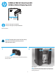
HP Color LaserJet Enterprise M855 and Flow MFP M880 - Hole Punch Kit Installation Guide

5
23
25
24
26
22
21
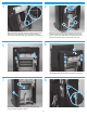
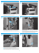
Remove the cover.
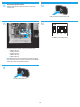
Disconnect three connectors (callout 1) on the controller PCA,
and then release the wire harnesses from one retainer (callout 2).
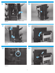
Remove two screws.
TIP: These screws fasten the rear sheet-metal support bracket to
the punch assembly. Use the hole provided in the chassis next to
the punch controller PCA to gain access to these screws.
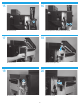
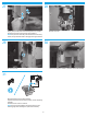
Slightly lift up on the punch hole assembly (callout 1), and then
disengage the sheet-metal support bracket (callout 2).
NOTE: The punch hole assembly is still fastened to the accessory
chassis, but you should be able to disengage the support bracket.
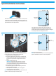
Remove two screws.
Slightly raise the front edge of the cover, and then slide the cover
towards the rear of the accessory to release it.