
User's Manual

3. Specify the X.25 circuit type—DDN, PDN, or PTOP (the default). (If
you don’t want PTOP, type ddn or pdn for the type of X.25 circuit,
then press [Return].)
• If you specified DDN for the circuit type, no more parameters are
needed for the default configuration. Go to step 4 on page 3-22.
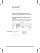
• If you specified PDN, you will need to enter the local DTE
address, the IP address, and the X.121 address, as follows:
Note Use the [Return] key to bypass fields that already contain default values.
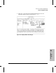
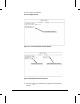
– Local DTE address for PDN: Type / l (the [/] and [L]
keys), enter the X.121 address of the local port at ‘‘Local DTE
Address’’, and press [Return] as many times as needed to return
to Quick Configuration. (Refer to figure 3-15 on page 3-21.)
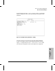
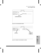
– IP address and X.121 address for PDN: Type / r, enter
the IP address and X.121 address of the remote port, and
press the [Return] key as many times as needed to return to the
Quick Configuration screen. (Refer to figure 3-16 on page
3-21.)
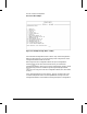
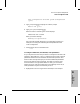
• If you specified PTOP, you will need to enter the local DTE
address, the remote DTE address, and the connection ID, as
follows:
– Local DTE address: Type / l (the [/] and [L] keys), enter
the X.121 address of the local port (at ‘‘Local DTE Address’’),
and press [Return] as many times as needed to return to the
Quick Configuration screen. (Refer to figure 3-17 on page
3-22.)
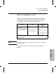
– Remote DTE address and Connection ID: Type / r,
enter the X.121 address (at ‘‘Remote DTE Addr’’) and the
Connection ID of the remote port, then use [Return] to return to
the Quick Configuration screen. (Refer to figure 3-18 on page
3-22.)
Note If you want to add more connection IDs, type / l instead of / r. Then
use [Return] to step past Local DTE Address. When you see ‘‘1. X.25
Virtual Circuits’’, type 1 and press [Return], then select the ‘‘Add’’ op-
tion. For more on how to use the Configuration Editor, refer to chapter 4.
How To Use Quick Configuration
How To Configure for X.25
3-20