EQ5 AC Drive Operations Manual Document: TWMC-EQ5OM Revision: 001P0
EQ5 AC Drive Operations Manual Preface Thank you for purchasing our EQ5 series inverter. This product is used to drive a 3-phase electric motor at variable speed. As incorrect use of this product may result in personal injury and/or property damage, please read all safety and operating instructions before using. Safety Instructions Please read this manual carefully before installing, connecting (wiring), operating, servicing, or inspecting the inverter.
EQ5 AC Drive Operations Manual Instructions on wiring: Danger • Connect the inverter to power via a line-protection molded-case circuit breaker or fuse, otherwise fire may result. • Always connect a ground wire, otherwise electric shock or fire may result. • A licensed specialist must perform the wiring, otherwise electric shock may result. • Turn off the power before starting the wiring, otherwise electric shock may result.
EQ5 AC Drive Operations Manual Instructions on maintenance, inspection, and replacement: Danger • Wait a minimum of five minutes (30HP/CT, 40HP/VT or less) or ten minutes (40HP/CT, 50HP/VT or more) after power has been turned off (open) before starting an inspection. (Also confirm that the charge lamp is off and that DC voltage between terminals P (+) and N (-) does not exceed 25V.) Otherwise electrical shock may result.
EQ5 AC Drive Operations Manual Compliance with UL/cUL standards [Applicable to products with UL/cUL mark] Caution Tightening torque and wire range: Refer to Table 2-3-5 in Section 2 Apply the following power supply specifications to the inverter: Inverter Model EQ5 - 20P2 - N1 to EQ5 - 2032 - N1 EQ5 - 2040 - C to EQ5 - 2150 - C EQ5 - 40P5 - N1 to EQ5 - 4032 - N1 EQ5 - 4040 - C to EQ5 - 4800 - C Maximum input voltage Input source current AC240V Not more than 100,000A AC480V Caution * * * * * * * * * *
EQ5 AC Drive Operations Manual Contents Pg. Before Using This Product ···························· 1 1-1 Receiving Instructions ·························· 1 1-2 Appearance ······································· 1 1-3 Handling the Product ························· 2-3 1-4 Carrying and Moving the Product ··········· 3 1-5 Storage ·········································· 3-4 2.
EQ5 AC Drive Operations Manual 1. Before Using This Product 1-1 Receiving Instructions Unpack and check the product as explained below. If you have any questions about the product, contact the nearest TWMC sales office or your local distributor where you purchased the unit. 1. Check the ratings on the nameplate to confirm that the delivered product is the one that was ordered.
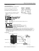
EQ5 AC Drive Operations Manual 1-3 Handling the Product 1. Removing the cover For drives rated 30HP/CT, 40HP/VT or less, loosen the mounting screws of the cover, then remove by pulling the top (see Fig. 1.3.1). Fig. 1-3-1 Removing the Surface Cover (for inverters rated 30HP/CT, 40HP/VT or less) For drives of 40HP/CT, 50HP/VT or more, first remove the six mounting screws, then remove the cover (see Fig. 1-3-2). Fig. 1-3-2 Removing the Surface Cover (for inverters rated 40HP/CT, 50HP/VT or more) 2.
EQ5 AC Drive Operations Manual For drives 40HP/CT, 50HP/VT or more, loosen the mounting screws of the digital operator and remove using the finger holds on the digital operator case (see Fig. 1-3-4). Fig. 1-3-4 Removing the Digital Operator (40HP/CT, 50HP/VT or more) 1-4 Carrying and Moving the Product 1. Carry the product by the main body. Do not carry the product while holding the cover or parts other than the main body. 2. Use a crane or hoist to carry a product equipped with handling hooks.
EQ5 AC Drive Operations Manual Long-term Storage If the product is to be stored for an extended period of time after purchase, the method of storage depends primarily on storage location. The general long-term storage method is as follows: 1. The above conditions for temporary storage must be satisfied. When the storage period exceeds three months, the upper limit of ambient temperature must be reduced to 30º (86ºF) to prevent the deterioration of the electrolytic capacitors. 2.
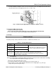
EQ5 AC Drive Operations Manual 2. Installation and Electrical Connections 2-1 Operating Environment Install this product in a location that meets the conditions listed in Table 2-1-1 Table 2-1-1 Operating Environment Table 2-1-2 Output Current Reduction Rate Based on Altitude Item Specifications Location Indoors Output current Altitude reduction rate -10Cº to +50ºC (14ºF to 122ºF) For products of 30HP/CT, 3300ft or lower (1000m) 1.00 40HP/VT or less, the ventilating Ambient 3300-4950ft 0.
EQ5 AC Drive Operations Manual 5. When installing this product in a control panel, ensure that the ventilation is sufficient to prevent the ambient temperature of the inverter from exceeding the specified value. Do not install the product in an area where there is inadequate ventilation, 6. If two or more inverters must be installed in the same equipment or control panel, arrange the units horizontally (side by side) to minimize the effect of heat.
EQ5 AC Drive Operations Manual *3 Do not use the bottom brackets in the bottom surface mount Installation. Fig. 2-2-3 40HP/CT, 50HP/VT or more Removing Upper and Lower Brackets 8. For inverters of 30HP/CT, 40HP/VT or less, remove the ventilating covers if ambient temperature exceeds +40°C (104°F) (1) Removing the ventilating covers: One ventilating cover is mounted on top of the inverter and the other two or three are mounted at the bottom. Fig.
EQ5 AC Drive Operations Manual 2-3 Electrical Connections To access the terminal blocks remove the cover in accordance with the instructions in this manual. 2-3-1 Basic Power Electrical Connections 1. Always connect input power to the main circuit power terminals L1/R, L2/S, and L3/T of the inverter. Check that the input voltage to be applied is within the maximum allowable voltage marked on the nameplate. 2. Always connect the power output terminals U, V, and W to the motor.
EQ5 AC Drive Operations Manual ______________________________________________________________________ TECO – Westinghouse Motor Company Basic Wiring Diagram 9
EQ5 AC Drive Operations Manual 2-3-2 Connecting the Input Power, Motor Output Power, and Ground Terminals The following shows the terminal arrangements for the various HP ranges of the EQ5. The terminal screw sizes are also shown for reference.
EQ5 AC Drive Operations Manual Screw size: M4 R0 T0 L1/R L1/R L2/S L2/S POWER INPUT L3/T L3/T P1 P1 U U V V MOTOR W W G G P(+) Screw size: G M10 – Other Terminals M12 P(+) N(-) N(-) 500 – 600 HP 460 VAC Screw size: M4 R0 T0 L1/R L1/R L2/S L2/S POWER INPUT L3/T L3/T Screw size: G M10 – Other Terminals M12 P1 P1 P(+) P(+) N(-) N(-) U V U W V MOTOR G W G 700 – 800 HP 460 VAC Table 2-3-1 Functions of Main Circuit Terminals and Ground Terminals Symbol Terminal Name D
EQ5 AC Drive Operations Manual 2. Inverter output terminals (U, V, W) a. Connect these terminals to a 3-phase motor in the correct phase sequence. If the direction of motor rotation is incorrect, swap any two of the U, V, and W phases. b. Do not connect a power factor correction capacitor or surge suppressor to the inverter output. c.
EQ5 AC Drive Operations Manual b. When the RCD (Residual-current Protective Device) is installed (30HP/CT, 40HP/VT or less), the terminal R0 and T0 should be connected to the output side of the RCD. If they are connected to the input side, the RCD will malfunction because the power supply of the inverter is three phase and the R0 and T0 input is single phase. If it is required to connect terminals R0 and T0 are to the input side of the RCD, an isolation transformer is required as shown on the Fig. 2-3-2.
EQ5 AC Drive Operations Manual DANGER- When terminals P (+) and N (-) of the inverter are not used, leave terminals open. If P(+) is connected to N (-) the bus voltage will be shorted, or if braking resistor is connected directly, the resistor can cause fire. d. Auxiliary contacts 1 and 2 of the braking unit are polarity sensitive. To connect the braking unit, refer to the "TECO Inverter Speecon Braking Unit Manual”. Fig. 2-3-5 Connection (15HP or more) 7.
EQ5 AC Drive Operations Manual NOTES ______________________________________________________________________ TECO – Westinghouse Motor Company Power Terminal Designations & Wiring 15
EQ5 AC Drive Operations Manual The connectors are mounted on the power PCB above the control PCB as shown on the right. Note: To remove a connector, squeeze the locking mechanism and pull. To mount a connector, push the connector down until it locks (clicks). EQ5-4040-C to EQ5-4200-C EQ5-2040-C to EQ5-14150-C EQ5-4250-C to EQ5-4900-C When shipped from the factory, CN UX is connected to U1 and CN RXTX is connected to L1/R-L3/T. Fig.
EQ5 AC Drive Operations Manual 2-3-3 Connecting the Control Terminals Table 2-3-3 lists the functions of the control circuit terminals. The connections to the control terminals will be in accordance with its function setting. Table 2-3-3 Control Terminal Functions Terminal Classification Terminal Name Symbol Potentiometer 13 power supply 12 Voltage input 1 V2 Voltage input 2 Analog input Function Supplies +10V DC to an externally connected frequency control potentiometer (1 to 5kΩ).
EQ5 AC Drive Operations Manual FWD REV X1 X2 X3 X4 X5 X6 X7 X8 X9 Forward operation / stop command Reverse operation / stop command Digital input 1 Digital input 2 Digital input 3 Digital input 4 Digital input 5 Digital input 6 Digital input 7 Digital input 8 Digital input 9 Digital input Forward operation (when FWD-CM is on) or deceleration and stop (when FWD-CM is open). Reverse operation (when REV-CM is on) or deceleration and stop (when REV-CM is open).
EQ5 AC Drive Operations Manual Pulse output FMP (CM Com) Y1 Y2 Y3 Y4 Frequency monitor (pulse output) Transistor output1 Transistor output2 Transistor output3 Transistor output4 Outputs a pulse frequency indicating the same as that of the analog FMA signal. A running signal, frequency equivalence signal, overload early warning signal, and other signals from the inverter are output (as a transistor output) to terminals Y1-Y4. For details, see "Setting the Terminal Functions E20 to E23" in Section 5.
EQ5 AC Drive Operations Manual (2) Digital input terminals (FWD, REV, X1 to X9, and CM) a. Digital input terminals FWD, REV and X1 to X9 are generally turned on or off by switching the input to (P24) +24V (source logic) or to (CM) 0V (sink logic). If the digital input terminals are turned on or off by a PLC with open collector using an external power supply, a resulting bypass circuit may cause the inverter to malfunction. To prevent this, connect the PLC terminal as shown in Fig. 2-3-10. b.
EQ5 AC Drive Operations Manual Fig.
EQ5 AC Drive Operations Manual 2-3-4 Input Protective Device Ratings. Input Voltage 230 VAC 460VAC HP Rating (VT / CT) 0.25 / 0.25 0.5 / 0.5 1/1 2/2 3/3 5/5 7.5 / 5 10 / 7.5 15 / 10 20 / 15 25 / 20 30 / 25 30 / 30 40 / 30 50 / 40 60 / 50 75 / 60 100 / 75 125 / 100 150 / 125 0.5 / 0.5 1/1 2/2 3/3 5/5 7.5 / 5 10 / 7.
Input Voltage EQ5 AC Drive Operations Manual 230 VAC 460 VAC 2-3-5 EQ5 Terminal Tightening Torque and Cable Size Terminal Tightening Torque Cable Size AWG (Note 3) Ib – in (Nm) (Note 4) HP L1/R, DB DC Rating DB Cir. L2/S, Circuit R0 L1/R, Reactor, P(+), N(-) L3/T, U, E (G) P(+), N(-) & L2/S & U, V & W (CT / VT) P1 & & DB V, W, P1 & DB T0 L3/T (Note 1) P(+) & P(+) (Note 1) 0.25 / 0.25 0.5 / 0.5 1/1 2/2 3/3 5/5 5 / 7.5 7.
EQ5 AC Drive Operations Manual 2-3-6 DC Link Choke Wattage Loss Fig. 2-3-12 DC Link Choke Note: Please refer to Sec. 8- 3- 4 for dimensions and weights. Input Voltage 230V 460V Hp 100/75 125/100 150/125 100/75 125/100 150/125 200/150 250/200 300/250 350/300 400/350 450/350 500/400 600/450 700/500 800/600 Model No.
EQ5 AC Drive Operations Manual 3. Initial Operation 3-1 Inspection and Preparation Before Operation Check the following before operation: 1. Check that all the electrical connections are secure and correct. (Fig. 3-1-1) In particular, check that the input power supply is not connected to any of the U, V, and W output terminals to the motor and that the ground terminal is securely grounded. 2. Check for short-circuits and ground faults between the terminals and powered–up sections. 3.
EQ5 AC Drive Operations Manual Table 3-2-1 General Methods of Operation Operation Frequency Operation mode setting command Operation using keypad 4. Power down the inverter and following safety precautions, connect the motor. Power-up the drive and repeat steps 1-3 and check the following. a. Is the direction of rotation correct? b. Is the motor rotating smoothly with no buzzing or abnormal vibration ? Operation using external signal terminals Keys on digital operator Freq.
EQ5 AC Drive Operations Manual 4. Digital Operator The Digital Operator has various functions for inputting, controlling, and displaying operations such as frequency setting, run/stop command, confirming and changing function data, confirming status, and copying. Please review and become familiar with each function before attempting to operate the drive. The Digital Operator can be removed or inserted during inverter operation, however, if it is removed during a keypad operation (e.g.
EQ5 AC Drive Operations Manual Operation Key Table 4-1-1 Functions of Operation Keys Main Function Used to switch the current screen display to the menu screen or switch to the initial display screen in the operation/trip mode. Used to switch the LED monitor or to determine the entered frequency, function code, or data. Used to change data, move the cursor up or down, or scroll the display screen. STOP STOP + RESET Used to move the cursor horizontally when changing data.
EQ5 AC Drive Operations Manual Table 4-2-1 Overview of Contents Displayed for Each Level No. 1 2 Level Name Operating mode Program menu Content This screen is for normal operation. Frequency setting by keypad panel and the LED display switching are possible only when this screen is displayed. No 1 DATA SET 2 DATA CHECK 3 OPR MNTR 4 I/O CHECK 5 MAINTENANCE 6 LOAD FCTR 7 ALM INF 8 9 3 4 Menu name Outline The code and name of the functions are displayed.
EQ5 AC Drive Operations Manual 4-3 Digital Operator Keypad Navigation 4-3-1 Operation Mode The LCD screen for normal inverter operation displays the inverter operating status and an operation guide. A second screen is available which graphically displays the operating status in the form of a bar graph. Switching between screens is possible by setting the value of parameter E45 (=1 operation guide), (=2 bar graph).
EQ5 AC Drive Operations Manual When stopped While running (E44 =0,1) (E44 = 0) (E44 = 1) E43 Setting Output frequency 1 (before slip 0 frequency compensation) Setting 1 Output frequency 2 (after slip compensation) frequency Setting 2 Setting frequency frequency 3 Output current Output current Output voltage 4 Output voltage (specified value) (specified value) Synchronous 5 speed setting Synchronous speed value Line speed 6 Line speed setting value Load rotation 7 speed setting Load rotation speed value Tor
EQ5 AC Drive Operations Manual 4-3-5 Setting the Parameter (function code) Value On the program menu screen, select 1. DATA SET as in para. 4-3-3. The parameter select screen appears. Select the desired parameter and set value as follows. RUN PRG PRG F/D LED FWD MENU SHIFT The parameter designations (function codes) consist of alphanumeric characters with unique alphabetical letters assigned to each parameter group as in table 4-3-1 below.
EQ5 AC Drive Operations Manual Display LINK ACTIVE NO SIGNAL(WE) DATA PRTCTD INV RUNNING FWD/REV ON Table 4-3-2 Reason for No Modification To Enable Data Change Currently writing from RS-485/RTU Send a cancel command to function option to function is being made. writing from RS-485/RTU. Stops a “write” operation from the link. The edit enabling command For functions E01 to E09, turn data function is selected using a terminal 19 (edit enabling general-purpose input terminal. command selection) ON.
EQ5 AC Drive Operations Manual Input Status via Terminals RUN PRG PRG F/D LED FWD PRG MENU SHIFT 1.DATA SET 2.DATA CHECK 3.OPR MNTR 4.I/O CHECK FUNC DATA Output Terminal Status Y1 Y2 Y3 Y4 COMM FWD REV X1 Y5 + XX.XV + XX.XV + XX.XV + XX.XV XX.XV XX.XmA XXXXH XXH X6 X7 X8 X9 X2 X3 X4 X5 X6 X7 X8 X9 Analog Input Current Value Terminal 12 Input Terminal 22 Input (AIO Option) Terminal 32 Input (AIO Option) Terminal V2 Input C1 = C2 = XX.XmA XX.
EQ5 AC Drive Operations Manual RUN PRG PRG F/D LED FWD MENU SHIFT NOTES _______________________________________________________________________ TECO – Westinghouse Motor Company Checking Maintenance Information 35
EQ5 AC Drive Operations Manual RUN PRG PRG F/D LED T= 3600s Imax = Iave = BPave = FWD MENU SHIFT Measuring Time 0.00A 0.00A 0.0% Set Measuring Time (0 – 3600 sec.) Use these keys to set measuring time Start Measuring Ex.- Set for 600 sec. T= 600s Imax = Iave = BPave = T= 150s Imax = Iave = BPave = 0.00A 0.00A 0.0% Displays remaining measurement time. When = 0 measurement ends. T= 3600s Imax = Iave = BPave = 56.4A 23.5A 10.
EQ5 AC Drive Operations Manual RUN PRG PRG F/D LED FWD MENU SHIFT _______________________________________________________________________ TECO – Westinghouse Motor Company Alarm Information 37
EQ5 AC Drive Operations Manual RUN PRG PRG F/D LED FWD MENU SHIFT Alarm Code of the selected alarm LOW SUP V PWR FAILURE EXCESS LOAD PHASE LOSS PRG 5.MAINTENANCE 6.LOAD FCTR 7.ALM INF 8.ALM CAUSE FUNC DATA FUNC DATA 0 / 1= LU -1= -----2= -----3= ----- Latest Alarm Alarm History Select an alarm To be displayed Display Example: Latest alarm LU is selected.
EQ5 AC Drive Operations Manual Select Data Copy (DATA COPY) on the main menu screen. Press to access the Data Copy (READ) screen. Press to read data from inverter 1. When complete, remove the Digital Operator and attach to inverter 2. Power up and again select 9. Press . On the Data Copy screen press to select (WRITE). Press . When complete the data transfer done.
EQ5 AC Drive Operations Manual Error Processing Verify Data 1. Data Change Disabled During Operation RUN PRG PRG F/D LED FWD MENU SHIFT If a write operation is attempted during a drive operation, or vice versa, the error message below will appear. After stopping the drive and pressing RESET retry the operation. PRG 30 HP-2 WRITE INV RUNNING 6.LOAD FCTR 7.ALM INF 8.ALM CAUSE 9.DATA COPY FUNC DATA 2. Memory Error If a write operation is attempted while data has not been saved (i.e.
EQ5 AC Drive Operations Manual 5. 5 No. 5 alarm 4. 4 No. 4 alarm 3. 3 No. 3 alarm 2. 2 No. 2 alarm 1. 1 No. 1 alarm (more than two alarms have occurred.
EQ5 AC Drive Operations Manual 5. Parameters F,E,C,P,H, A and U This section covers parameters F,E,C,P,H, A and U which can be set via the digital operator (see Sect. 4) to achieve a specific performance for a particular application. For most general purpose applications, the factory settings are sufficient and will not need to be changed. If the parameter values are to be changed, it is recommended that resulting overall drive performance be evaluated to avoid any unwanted performance issues.
EQ5 AC Drive Operations Manual E Parameters Min. Para. No. NAME LCD Display Setting range Unit Unit Factory setting 30HP/CT 40HP/VT 40HP/CT 50HP/VT Change User During Remark Set value Oper.
EQ5 AC Drive Operations Manual Min. Para. No. NAME LCD Display Setting range Unit Unit Factory setting 30HP/CT 40HP/VT 40HP/CT 50HP/VT Change User During Remark Set value Oper. C20 JOG frequency C20 JOG Hz 0.00 to 120.00Hz C21 PATTERN (Mode select) C21 PATTERN 0,1,2 Hz 0.01 5.00 N - - 0 C22 (Stage 1) C22 STAGE 1 N C23 (Stage 2) C23 STAGE 2 C24 (Stage 3) C24 STAGE 3 C25 (Stage 4) C25 STAGE 4 C26 (Stage 5) C26 STAGE 5 0.00 F1 C27 (Stage 6) C27 STAGE 6 0.
EQ5 AC Drive Operations Manual A Parameters Min. Para. No. NAME LCD Display Setting range Unit Unit Factory setting 30HP/CT 40HP/VT 40HP/CT 50HP/VT Change During Oper.
5-2 Function Explanation F:Fundamental function F00 Data protection Setting can be made so that a set value cannot be changed by keypad panel operation. F 0 0 D A T A Setting range P R T C Related functions E01 to E09 (Set values 19) Forward / Inverse operation Forward operation (set value: 1, 3, 4, 5) Frequency setting value Maximum frequency 0 : The data can be changed. 1 : The data cannot be changed.
LE Frequency setting F01 C30 Feedback selection Hz2/Hz1 H21 Frequency setting by keypad panel Frequency setting signals 12 Gain Bias C31 C32 H25 Feedback filter #0 #4 + #3 + #2 Gain C1 V2 + #7 + V1 + PID control Bias frequency F17 F18 Negative polarity prevention H20 Operation selection #1,#2,#3,#6,#7 H22 Proportional H23 Integral H24 Differential Inverse #6 operation Inverse #5 Forward/ Reverse operation + #1,#5 operation Limit signal Opti
F03 Maximum frequency 1 This function sets the maximum output frequency for motor 1. This is a function for motor 1. F 0 3 M A X H z Setting range EQ5: - 1 50 to 120Hz Setting a value higher than the rated value of the device to be driven may damage the motor or machine. Match the rating of the device. F04 Base frequency 1 This function sets the maximum output frequency in the constant-torque range of motor 1 or the output frequency at the rated output voltage. Match the rating of the motor.
F09 Torque boost 1 This is a function for motor 1. The following can be selected: F 0 9 T R Q B O O S T 1 Selection of load characteristics such as automatic torque boost, square law reduction torque load, proportional torque load, constant torque load. -- Enhancement of torque (V/f characteristics), which is lowered during low-speed operation. Insufficient magnetic flux of the motor due to a voltage drop in the low-frequency range can be compensated.
75HP 125HP 110kWto or above Operation level current (%) (%) 100 90 85 F13 Electric thermal O/L relay (for breaking resistor) (When F10 = 1) 53 fb (fb60Hz) 60Hz (fb60Hz) fb:Base frequency fe= This function controls the frequent use and continuous operating time of the braking resistor to prevent the resistor from overheating. Related functions: U59 F 1 3 D B R O L Inverter capacity fe Output frequency f0 (Hz) Operation level current and output frequency Fe x 0.33 Fe x 0.
F14 Restart mode after momentary power failure This function selects operation if a momentary power failure occurs. The function for detecting power failure and activating protective operation (i.e., alarm output, alarm display, inverter output cutoff) for undervoltage can be selected. The automatic restart function (for automatically restarting a coasting motor without stopping) when the supply voltage is recovered can also be selected.
Power failure Power failure Power recovery Set value : 3 Set value : 0 Main circuit DC voltage Power recovery H15 Operation continuation level Main circuit DC voltage Under voltage Time Output frequency Output frequency (motor speed) LV trip ON LV trip Set value : 1 Main circuit DC voltage Output (terminals Y1 to Y5) Under voltage Set value : 4 Time Output frequency LV trip Set value : 2 ON H15 Operation continuation level Main circuit DC voltage Output frequency Under voltage Synchr
F15 Frequency limiter (High) F16 Frequency limiter (Low) This function sets the upper and lower limits for the setting frequency . F 1 F 1 5 H 6 L L L Setting range EQ5: I I M M I I T E R T E R 0 to 120Hz F18 Bias frequency This function adds a bias frequency to the set frequency value to analog input. F 1 8 F R E Q B I A S Setting range EQ5: -120.0 to +120.0Hz The operation follows the figure below.
F23 Starting frequency F24 Start frequency F25 (frequency) (Holding time) Stop frequency The starting frequency can be set to reserve the torque at startup and can be sustained until the magnetic flux of the motor is being established. Frequency: This function sets the frequency at startup. F 2 3 S T A R T Setting range: H z 4 H O L D I N G t This function sets the frequency at stop. Setting range: F30 FMA (voltage adjust) F31 FMA (function) Monitor data (e.g.
F36 F33 FMP (pulse rate) F34 FMP (voltage adjust) F35 FMP terminal (function) Monitor data (e.g.,output frequency, output current) can be output to terminal FMP as pulse voltage. Monitor data can also be sent to an analog meter as average voltage. When sending data to a digital counter or other instrument as pulse output, set the pulse rate in F33 to any value and the voltage in F34 to 0%.
WARNING When the torque limit function is selected, an operation may not match the set acceleration and deceleration time or set speed. The machine should be so designed that safety is ensured even when operation does not match set values. Otherwise accidents may result. WARNING The frequency may be stagnated / held constant when using the automatically OU trip prevention and set the frequency limit(Low) to the setting frequency or less. Otherwise accidents may result.
E: Extension Terminal Functions E01 ~ X1 Terminal function ~ E09 X9 Terminal function Each function of digital input terminals X1 to X9 can be set as codes.
Coast-to-stop command [BX] When BX and P24 are connected, inverter output is cut off immediately and the motor starts to coast-to-stop. An alarm signal is neither output nor self-held. If BX and P24 are disconnected when the operation command (FWD or REV) is on, operation starts at the start frequency. To use this BX terminal function, assign value "7" to the target digital input terminal.
Torque limit 2/torque limit 1 [TL2/TL1] This function switches the torque limit value set in function codes F40 and F41, and E16 and E17 by an external digital input signal.
Inverse mode changeover [IVS] The analog input (terminals 12 and C1) can be switched between forward and inverse operations by an external digital input signal. Set value Related function input signal Function selected F01, C30 21 Forward operation when forward operation is set and vice versa Inverse operation when forward on operation is set and vice versa This function is invalid when the PID control is selected(H20: 1 or 2).
Related functions E01 to E09 (Set values:14) Frequency setting 1 / Frequency setting 2 [Hz1/Hz2] This function switches the frequency setting method set in function codes F01 and C30 by an external digital input signal. This is the reverse-logic of setting value "11"(Frequency setting 2/Frequency setting 1 [Hz2/Hz1]). Set value input signal Frequency setting method selected 35 C30 FREQ CMD2 off F01 FREQ CMD1 on Note: It can not be used with set value "11" simultaneously.
E20 Y1 terminal function ~ ~ Frequency equivalence signal [FAR] Y5A and Y5C terminal function E24 Some control and monitor signals can be selected and output from terminals [Y1] to [Y5]. Terminals [Y1] to [Y4] use transistor output; terminals[Y5A] and [Y5C] use relay contacts. See the explanation of function code E30 (frequency arrival [detection width]). Frequency level detection [FDT1] See the explanation of function codes E31 and E32 (frequency detection).
Inverter stopping [STOP] This function outputs an inverted signal to Running (RUN) to indicate zero speed. An ON signal is output when the DC injection brake function is operating. Ready output [RDY] This function outputs an ON signal when the inverter is ready to operate. The inverter is ready to operate when the main circuit and control circuit power is established and the inverter protective function is not activating. About one second is required from power-on to ready for operation in normal condition.
In the following cases, normal life judgment of the capacitor in main circuit may not be able to be performed. 1. When a power is turned off during inverter operation. 2. When cooling fan ON/OFF control is operated. ( function code : H 06= 1) 3. When the power is supplied by the auxiliary input terminals (R0,T0). 4. When the option card is operated . 5. When RS-485 communication is operated . 6. When the power supply is turned off with digital input (FWD, REV, X1-X9) of a control terminal being ON.
E33 OL function signal (mode select) Select one of the followingselection two types of overload early warning: early warning by electronic thermal O/L relay function or early warning by output current. E 3 3 O L W A R N I N G Set value 0: Electronic thermal O/L relay 1: Output current Set Function Description value Electronic 0 Overload early warning by electronic thermal thermal O/L relay (having inverse-time O/L relay characteristics) to output current.
E43 LED monitor (function) E44 LED monitor (display at stop mode) The data during inverter operation, during stopping, at frequency setting, and at PID setting is displayed on the LED. Display during running and stopping During running, the items selected in "E43 LED monitor (display selection)," are displayed. In "E44 LED monitor (display at stopping)," specify whether to display some items out of the set values or whether to display the same items as during running.
C:Control Functions of Frequency Internal set frequency (Hz) C01 Jump frequency 1 C02 Jump frequency 2 C03 Jump frequency 3 C04 Jump frequency (Hysteresis) Actual jump width Jump frequency width This function makes the set frequency jump so that the inverter's output frequency does not match the mechanical resonance point of the load. Up to three jump points can be set. This function is ineffective when jump frequencies 1 to 3 are set to 0Hz.
C20 JOG frequency C22 This function sets the frequency for jogging operation of motor, which is different from the normal operation. C 2 0 J O G H z Setting range EQ5 : 0.00 to 120.00 Hz Starting with the jogging frequency is combined with jogging select signal input from the keypad panel or control terminal. For details, see the explanations of "E01 Terminal X1" to "E09 Terminal X9.
Pattern operation setting example Set value Function Operation frequency to be set C21 (operation selection) 1 C22 (stage 1) 60.0F2 Multistep frequency 1 (C05) C23 (stage 2) 100F1 Multistep frequency 2 (C06) C24 (stage 3) 65.5R4 Multistep frequency 3 (C07) C25 (stage 4) 55.0R3 Multistep frequency 4 (C08) C26 (stage 5) 50.0F2 Multistep frequency 5 (C09) C27 (stage 6) 72.0F4 Multistep frequency 6 (C10) C28 (stage 7) 35.0F2 Multistep frequency 7 (C11) The following diagram shows this operation.
Analog signals input from control terminal 12 or C1 may contain noise, which renders control unstable. This function adjusts the time constant of the input filter to remove the effects of noise. C 3 3 R E F F I L T E R Setting range: 0.00 to 5.00 seconds An excessive setting delays control response though stabilizing control. A set value too small speeds up control response but renders control unstable. If the optimum value is not known, adjust the setting when control is unstable or response is delayed.
Motor 1 (P: Motor Parameters) P01 Number of motor 1 poles This function sets the number of poles of motor 1 to be driven. If this setting is not made, an incorrect motor speed (synchronous speed) is displayed on the LED. P 0 1 M 1 P O L E S Set values: 2, 4, 6, 8, 10, 12, 14 P02 Motor 1 (capacity) The nominal applied motor capacity is set at the factory. The setting should be changed when driving a motor with a different capacity.
Note1: If REMOTE operation(F02: 1) is selected, operation signal is given from terminal [FWD] or [REV]. Note2: Use function "A13 Motor 2 (auto tuning)," to tune motor 2. In this case, set values described in 1 and 2 above are for the function (A01 - ) of motor 2. When the auto tuning value is set to 2, the motor rotates at a maximum of half the base frequency. Beware of motor rotation. Otherwise injury may result. WARNING P05 When connecting a reactor or filter to the output circuit, add its value.
High Performance functions (H:High Performance function) H03 Data initializing This function returns all function data changed by the customer to the factory setting data. (initialization). H 0 3 D A T A I N I T Set value 0: Disabled. 1: Initializing data. To perform initialization, press the STOP and keys together to set 1, then press the FUNC key. The set DATA values of all functions are initialized. The set value in H03 automatically returns to 0 following the end of initialization.
H07 ACC/DEC (Mode select) pattern This function selects the acceleration and deceleration pattern. H 0 7 A C C Set value 0: 1: 2: 3: Output frequency Acceleration time P T N Inactive (linear acceleration and deceleration) S-shape acceleration and deceleration (mild) S-shape acceleration and deceleration (*) Curvilinear acceleration and deceleration Base frequency Related functions U02 to U05 0 H08 * The S-shape range is set by the function: U02 to U05 when the set value "2" is selected.
H09 Start mode This function smoothly starts the motor which is coasting after a momentary power failure or after the motor has been subject to external force, without stopping motor. At startup, this function detects the motor speed and outputs the corresponding frequency, thereby enabling a shock-free motor startup.
H13 Auto-restart (Restart time) Instantaneous switching to another power line (when the power of an operating motor is cut off or power failure occurs) creates a large phase difference between the line voltage and the voltage remaining in the motor, which may cause electrical or mechanical failure. To rapidly switch power lines, enter the remaining voltage attenuation time to wait for the voltage remaining in the motor to attenuate. This function operates at restart after a momentary power failure.
H20 ~ PID control (Mode select) ~ H25 PID control (Feedback filter) H21 PID control detects the amount of control (feedback amount) from a sensor of the control target, then compares it with the target value (e.g., reference temperature). If the values differ, this function performs a control to eliminate the deviation. In other words, this control matches the feedback amount with the target value.
PID control (P-gain) H23 PID control (I-gain) H24 PID control (D-gain) These functions are not generally used alone but are combined like P control, PI control, PD control, and PID control. P operation Operation using an operation amount (output frequency) proportional to deviation is called P operation, which outputs an operation amount proportional to deviation, though it cannot eliminate deviation alone.
Response -To suppress vibration with a frequency roughly equivalent to the value "H24 D-gain," decrease the value of H24. If there is residual vibration with 0.0, decrease the value of "H22 P-gain." Before adjustment After adjustment PID control (Feedback filter) This filter is for feedback signal input from terminal [12] or [C1]. This filter stabilizes operation of the PID control system. A set value that is too large, however, deteriorates response.
H30 Serial link (Function select) The link function (communication function) provides RS-485 (provided as standard) and bus connections (optional). The serial link function includes: 1) Monitoring (data monitoring, function data check) 2) Frequency setting 3) Operation command (FWD, REV, and other commands for digital input) 4)Write function data H 3 0 L I N K F U N C Setting range: 0 to 3 Communication can be enabled and disabled by a digital input.
Motor 2 (A: Alternative Motor Parameters) A01 Maximum frequency2 This function sets the maximum frequency for motor 2 output by the inverter. This function operates the same as "F03 Maximum frequency 1." For details, see the explanation for F03. A 0 1 M A X H z - 2 A02 Base frequency 2 This function sets the maximum output frequency in the constant-torque area of motor 2 (i.e., output frequency at rated output voltage). This function operates the same as "F04 Base frequency 1.
U : User function U01 Maximum compensation frequency during braking torque limit This function becomes effective, when the torque limit (brake) is used. The inverter controls to increase the output frequency so that torque calculations do not exceed the torque limit (brake) setting ( F41 or E17). (When F41 or E17 is set to 999, it becomes invalid.) This function sets the increment of upper limit for output frequency.
◆When you make measurement of capacity and life expectancy judgment of capacitor with an actual operating condition, set the value “30” to the function code “E20 to E24”. And write the measurement result U09 with an actual operating condition to the function code U08 as an initial value as early as possible since inverter operation starts. However, life judgment by the measurement result cannot be performed in case of 1 and 2 as below. 1. During inverter operation, a power supply is turned off and it stops.
becomes longer than the set deceleration time. ◆In case of F14 set value : 3. The output frequency is lowered by the control by which the DC voltage of the main circuit is kept constant from the regeneration energy, so that the inverter may continue operation when momentary power failure occurs. The response is adjusted with U23 and U24 at this time. ◆Calculate the integral gain using the following formula.
! CAUTION △ ◆Set the function code both “ F13” and “U59 ” before operating the inverter, and don’t change the functions during operation. The integrated thermal data are cleared immediately, when function code “ F13” or “U59 ” are changed. The overheat protection of resistor becomes invalid. When the function code “ F13” or “U59 ” are changed in the state where temperature rose, the overheat protection of resistor becomes invalid, too.
(Gain adjustment) 1) Drive the motor in an arbitrary frequency of about 10 to 60Hz (However, constant speed) after executing the above-mentioned offset adjustment. (U61:1) At this time, gain adjustment is available unrelated to the load state. 2) When the data of U61 is changed to "2", and the FUNC/DATA key is ON, the gain self adjustment is started. The display of “ storing" of the keypad panel disappears several seconds to 30 seconds later. When the set value returns to "0", adjustment is completed.
EQ5 AC Drive Operations Manual 6. Alarm Codes, Causes and Troubleshooting The drive’s built-in protective features protect the drive against operation outside its design limits. 6-1 Alarm Codes and Causes Upon activation of an Alarm, the LED display shows the alarm code and the motor coasts to a stop. A list of alarm codes and causes are shown in the following table.
EQ5 AC Drive Operations Manual Overheating of heat sink OH1 FIN OVERHEAT External alarm OH2 EXT ALARM Inverter internal overheating OH3 HIGH AMB TEMP Overheating of braking resistor dbH DBR OVERHEAT Motor 1 overload OL1 MOTOR1 OL Motor 2 overload OL2 MOTOR2 OL Inverter overload OLU INVERTER OL Blown fuse FUS DC FUSE OPEN Memory error Er1 MEMORY ERROR Digital Operator communication error Er2 KEYPD COM ERR CPU error Er3 CPU ERROR Er4 OPTN COM ERR Er5 OPTION ERROR Forced st
EQ5 AC Drive Operations Manual DANGER If an alarm reset is activated when the operating signal is ON, the inverter can restart suddenly, which may be dangerous. To ensure safety to personnel, disable the operating signal before resetting the alarm.
EQ5 AC Drive Operations Manual 6-3.Trouble shooting 6-3-1 Protective function activation (1) Overcurrent Overcurrent during acceleration OC1 Remove the short-circuit and ground fault. YES Overcurrent during deceleration OC2 Are the motor connecting terminals (U, V, W) short-circuited or grounded? NO NO Reduce the load or increase YES the inverter capacity.
EQ5 AC Drive Operations Manual (4) Overvoltage Overvoltage during acceleration OU1 Reduce the supply voltage to less than the specified upper limit.
EQ5 AC Drive Operations Manual (6) Overtemperature at inside air (6) overheating Overtemperature at inside air and at heatsink. (7) External thermal relay tripped and overheating at heatsink.
EQ5 AC Drive Operations Manual (9) Memory error Er1, (9) Memory error Er1, Keypad panel communication error Er2,CPU Keypad panel communication error Er2, error CPUEr3 error Er3 (10) Output wiring error (10) Output wiring error Er1,2,3 indicated. Abnormal display or indication goes out. Output wiring error Er7 Are the braking unit and braking resistor connected incorrectly? YES Connect correctly the cable. NO Turn the power off then on again after the CHARGE lamp (CRG) goes off.
EQ5 AC Drive Operations Manual 6-4 Abnormal motor rotation (1) If motor does not rotate Charge lamp (CRG) NO lights and LCD monitor lights up? Motor does not rotate. Are the circuit breaker and NO magnetic contactor on the power supply side switched on? YES Remove the cause of alarm function activation and reset the alarm, then run the motor.
EQ5 AC Drive Operations Manual (2) If the motor rotates but the speed does not change Is the maximum frequency setting too low? The motor rotates but the speed does not change. YES Increase the setting. NO Change the setting. YES NO YES Pattern operation Is the timer timing too long? NO YES Set the frequency.
EQ5 AC Drive Operations Manual (3) If the motor stalls during acceleration The motor stalls during acceleration. Is the acceleration time too short? YES Prolong the time. NO Is the inertia moment of the motor or the load excessive? YES Reduce the torque of the load or increase the inverter capacity. YES Contact TWMC. NO NO Use a thicker cable YES between the inverter and the motor or shorten the cable length.
7. Maintenance and Inspection It is recommended that daily and periodic inspections be carried out to insure trouble-free operation and long-term reliability. The following are recommendations for conducting these inspections. 7-1 Daily Inspection During operation, a visual inspection for abnormal operation can be completed externally without removing the covers. The inspections should cover the following: (1) The performance is as expected and is within specifications.
Terminal block Is there damage? 1) Is there electrolyte leakage, discoloration, crazing, or swelling of the case? 2) Is the safety valve not protruding or are valves protruding too far? 3) Measure the capacitance if necessary.
1) Determination of the capacitance of the main circuit capacitors. This inverter is equipped with a function to automatically indicate the capacitance of the capacitors in the main DC circuit when powering up the drive after disconnecting the power according to the prescribed conditions. The initial capacitance values are set in the inverter when shipped from the factory, and the decrease ratio (%) to those values can be displayed. Use the procedure as next described.
Inspection Notes and Records DATE ITEM ________________________________________________________________________________ _______________________________________________________________________ TECO – Westinghouse Motor Company Inspection Notes & Records 100
EQ5 AC Drive Operations Manual 7-3 Main Circuit Voltage, Current, and Power Measurements. When making main circuit voltage and current measurements, the resulting values depend on the type of meter used due to the harmonic component included in the voltage and current of the main circuit power (input) and the output (motor) side of the inverter. When measuring with a meter for commercial power frequency, use the meters shown in Table 7-3-1.
EQ5 AC Drive Operations Manual 7- 4 Insulation Test It is not necessary to do an insulation test on the inverter as this was completed at the factory. If an insulation test with a megger test must be completed, then proceed as described below as an incorrect testing method may result in product damage. If a dielectric strength test must be completed, the specifications for the test must be followed as Improper testing may result in damage to the inverter.
EQ5 AC Drive Operations Manual 7-6 Inquiries About Damaged Products If there is damage, a fault in the product, or questions concerning the product, contact your local distributor or nearest TWMC sales office with the following information: a - Inverter type (Model No.) b - Serial No. (equipment serial number) c - Purchase date d - Problem details (e.g.
EQ5 AC Drive Operations Manual 8.
EQ5 AC Drive Operations Manual EQ5 CT (Constant Torque) – 460V Series Nema 1 Type Applied Motor Nominal (HP) Input ratings Output ratings Type EQ5-4XXX-XX Rated capacity [kVA] (*1) Rated output current [A] (*2) Overload capability Starting torque Rated output Voltage [V] (*3) Rated output frequency [Hz] Phases, voltage, frequency Voltage/frequency variations Momentary voltage dip capability (*6) Required power supply capacity [kVA] (*7) 0.5 1 2 3 5 5 Open Chassis 7.
EQ5 AC Drive Operations Manual (*4) The taps within the inverter must be changed for an input power supply rated at 380 to 398V/50 Hz or 380 to 430V/60 Hz. (*5) If the imbalance between phases exceeds 2%, use a power-factor correcting DC reactor (DCR). Imbalance rate between phases [%] = ( Max. Voltage [V] - Min.
EQ5 AC Drive Operations Manual 8-2 Common Specifications Output frequency Item Explanation Control method Maximum frequency Base frequency Starting frequency Carrier frequency Accuracy (stability) Control Setting resolution Voltage/frequency characteristics Torque boost Accelerating/decelerating time DC injection braking Function equipped Operation Operation method Frequency setting Operation status output signals Indication Digital display (LED) Liquid crystal display (LCD) Language Lamp displ
EQ5 AC Drive Operations Manual 8-3 Dimensions and Weights 8-3-1 230V and 460V Series NEMA 1 (up to 30HP/CT, 40HP/VT ) 230 V Series NEMA 1 Dimensions Inches / mm Wt. Lbs. / kg Model EQ5- 2XXX-N1 H W D 0P2 & 0P5 10.2/260 4.33/110 5.12/130 0.28/7 9.69/246 0.28/7 3.78/96 0.24/6 0.24/6 001 10.2/260 4.33/110 5.71/145 0.28/7 9.69/246 0.28/7 3.78/96 0.24/6 0.24/6 5.5/2.5 002,003 & 005 10.2/260 5.90/150 5.71/145 0.28/7 9.69/246 0.28/7 5.35/136 0.24/6 0.24/6 8.4/3.
EQ5 AC Drive Operations Manual 8-3-2 230V and 460V Series Open Chassis (30 – 350HP CT and 40 – 450HP VT) Model EQ5- 2XXX-C 40 & 50 60 75 & 100 125 150 Model EQ5- 4XXX-C 40 & 50 60 75 & 100 125 150 & 200 250 & 300 350, 400 & 450 230 V Series Open Chassis Dimensions Inches (mm) W W1 W2 13.4 (340) 14.8 (375) 14.8 (375) 20.9 (530) 26.8 (680) 9.45 (240) 10.8 (275) 10.8 (275) 16.9 (430) 22.8 (580) 12.8 (326) 14.2 (361) 14.2 (361) 20.1 (510) 26.0 (660) W3 N/A 11.
EQ5 AC Drive Operations Manual 8-3-3 460V Series Open Chassis (400 – 600HP CT and 500 – 800HP VT) Model EQ5- 4XXX-C W W1 W2 W3 700 & 800 26.8 (680) 34.6 (880) 22.8 (580) 30.7 (780) 26 (660) 33.9 (860) 11.4 (290) 10.2 (260) Con’t D D1 D2 17.7 (450) 17.7 (450) 11.2 (285) 11.2 (285) 0.25 (6.4) 0.25 (6.4) 500 & 600 500 & 600 700 & 800 W4 Dimensions Inches (mm) W5 H H1 H2 H3 H4 H5 H6 H7 10.2 (260) 24 (610) 31.9 (810) 55.1 (1400) 55.1 (1400) 53.9 (1370) 53.9 (1370) 52.4 (1330) 52.
EQ5 AC Drive Operations Manual 8-3-4 DC Link Choke for (75 –600HP CT and 100 – 800HP VT) 230 V Series Open Chassis Inverter Model DC Choke EQ-2XXX-C Model Wt. lbs (kg) Dimensions Inches (mm) A B C D E F G H J Terminal hole size 100 DCR2-75B 7.87 (200) 6.69 (170) 3.94 (100) 5.55 (141) 4.33 (110) 2.76 (70) 0.39 (10) 8.27 (210) N/A M12 40 (18) 125 DCR2-90B 7.09 (180) 5.91 (150) 4.33 (110) 5.94 (151) 5.51 (140) 2.95 (75) 0.39 (10) 9.45 (240) 0.
EQ5 AC Drive Operations Manual 8-4 RS-485 Modbus RTU Serial Communications The serial communications interface supports operation, configuration and monitoring of inverter functions through an EIA/RS-485 connection. The serial interface is based on Modbus RTU protocol. This protocol allows the inverter to function as an RTU slave on an industrial network.
EQ5 AC Drive Operations Manual 8-4-5 Inverter Function Code Access All of the inverter function codes are accessible through the RS-485 serial interface. Inverter function codes are mapped to RTU holding registers. An inverter function code RTU address is 2 bytes in length. The high byte corresponds to a code that represents the inverter parameter sort (F–M). The low byte corresponds to the inverter parameter number within the sort (0 -99).
EQ5 AC Drive Operations Manual Function data Registers Address Code 1800 1801 S08 S09 1802 S10 1803 S11 Name Acceleration time F07 Deceleration time F08 Torque limit level 1 (driving) F40 Torque limit level 2 (braking) F41 Unit s s % % Variable Range 0.1–3600.0 0.1–3600.0 20.00 –200.00, 999 (EQ5:20.00-150.00) 0.00, 20.00–200.00, 999 (EQ5:20.00-150.00) Min. Unit 0.1 0.1 Read/ Write R/W R/W Data Format 3 3 1.00 R/W 5 1.
EQ5 AC Drive Operations Manual 2073 M25 ROM version 2074 M26 Transmission error processing code Frequency command at alarm (final 2075 M27 command) Frequency command at alarm (final 2079 M31 command) Actual frequency at alarm 2080 M32 2081 2082 2083 2084 M33 Actual torque at alarm M34 Torque current at alarm M35 Output frequency at alarm M36 Motor output at alarm (input power) Output current rms.
EQ5 AC Drive Operations Manual Data format [6] Decimal data (Positive, negative): Min. unit 0.01 Example: M07 (actual torque value)= - 85.38% - 85.38 X 100= - 8538=DEA6H Data format [7] Unsigned Decimal data (Positive): Min. unit 0.001 Example: If o05 (follow - up side ASR 1 constant) = 0.105s 0.105 X 1000 = 105 = 0069H Data format [8] Decimal data (Positive, negative): Min. unit 0.001 Example: Data = -1.234 - 1.234 X 1000 = - 1234 = FB2EH Data format [9] Unsigned Integer data (Positive): Min.
EQ5 AC Drive Operations Manual Data format [12] Index data (ACC/DEC time, display coefficient): 15 14 13 12 Polarity 0 0 0 0: Positive (+), 11 9 8 7 6 Index portion 0: 0.01 1: 0.1 2: 1 3: 10 1: Negative ( - ) 10 5 4 3 2 1 0 2 1 0 Data portion X X X X 001–999 100–999 100–999 100–999 (0.00–9.99) (10.0–99.9) (100–999) (1000–9990) Example: F07 (acceleration time 1) = 20.0 s 10.0 < 20< 99.9 → index =1 20.0 = 0.
EQ5 AC Drive Operations Manual Data format [16] Operating state: 15 14 BUSY 13 WR 12 RL 11 10 9 ALM DEC ACC 8 7 6 IL VL TL (All bit are ON or active by 1) FWD: Forward operation REV: Reverse operation EXT: DC braking active (or pre-excitation) INT: BRK: NUV: TL: VL: 5 4 3 NUV BRK INT 2 1 0 EXT REV FWD IL: ACC: DEC: ALM: RL: WR: Current limiting Under acceleration Under deceleration Inverter fault Transmission valid Function writing privilege 0: Keypad panel 1: RS-485 2: Fieldbus
EQ5 AC Drive Operations Manual Data format [20] Code 1 2 Transmission error code: Description FC (function code) error Illegal address Code 71 72 3 Illegal address (Data range error) 7 NAK -Priority for comm.
EQ5 AC Drive Operations Manual 9. Options The inverter supports two internally mounted cards. One option card is mounted under the main cover (Location A) and the other option card is mounted in a special adapter under the keypad (Location B). Only one card can be mounted in these locations. There are two different types of option cards, Type 1 and Type 2.
EQ5 AC Drive Operations Manual 10. Electromagnetic Compatibility (EMC) 10-1 General In accordance with the provisions described in the European Commission Guidelines Document on Council Directive 89/336/EEC, the EQ5 series of inverters is chosen to be classified as "Complex Components".
EQ5 AC Drive Operations Manual Inverter Model No. EQ5 – 40P5 – N1 EQ5 – 4001 – N1 EQ5 – 4002 – N1 EQ5 – 4003 – N1 EQ5 – 4005 – N1 EQ5 – 4007 – N1 EQ5 – 4010 – N1 EQ5 – 4015 – N1 EQ5 – 4020 – N1 EQ5 – 4025 – N1 EQ5 – 4030 – N1 EQ 5 - 4032 –N1 EQ 5 - 4040 –N1 EQ 5 - 4050 –N1 EQ 5 - 4060 –N1 EQ 5 - 4075 –N1 EQ 5 - 4100 –N1 EQ 5 - 4125–N1 EQ 5 - 4150 –N1 EQ 5 - 4200–N1 EQ 5 - 4250 –N1 EQ 5 - 4300–N1 EQ 5 - 4350 –N1 EQ 5 - 4400–N1 EQ 5 - 4450–N1 Filter Type Table 10-2-1 RFI filters Max.
EQ5 AC Drive Operations Manual Dimensions [inch(mm)] Filter Type RF3100-F11 RF3180-F11 W W1 H H1 D 7.87 (200) 7.87 (200) 6.54 (166) 6.54 (166) 17.1 (435) 19.5 (495) 16.1 (408) 18.4 (468) 5.12 (130) 6.30 (160) Fig.
EQ5 AC Drive Operations Manual Fig.10-2-3 Outline Dimensions Fig.10-2-4 Outline Dimensions Metal enclosure RCD or MCCB RFI Inverter L1 L1’ L2 L2’ L3 L3’ PE L1/R U L2/S V L3/T W Shielded motor cable Motor M Shielding must be electrically continuous and grounded at the cabinet and the motor. 3ph Power supply Fig.