
User Manual


EQ5 AC Drive Operations Manual
______________________________________________________________________
TECO – Westinghouse Motor Company Control Terminal Designations & Wiring 20
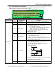
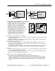
(2) Digital input terminals (FWD, REV, X1 to X9, and CM)
a. Digital input terminals FWD, REV and X1 to
X9 are generally turned on or off by switching
the input to (P24) +24V (source logic) or to
(CM) 0V (sink logic). If the digital input
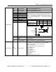
terminals are turned on or off by a PLC with
open collector using an external power supply,
a resulting bypass circuit may cause the
inverter to malfunction. To prevent this, connect
the PLC terminal as shown in Fig. 2-3-10.
b. When using a dry contact input such as a
relay, highly reliable contacts capable of
handling low level signals must be used.
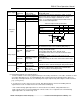
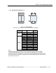
(3) Transistor output terminals (Y1 to Y4, CME)
a. Refer to the circuit configuration in Table 2-3-3 Transistor Output and confirm the polarity of the
external power supply.
b. When connecting a control relay to the transistor output, connect a transient absorbing diode
to both ends of the relays’ exciting coil.
(4) Sink or Source Logic selection
a. The slide switch SW1 located on the control board, sets the digital inputs for sink or source
input logic. The factory default is the sink position and is most commonly used in the US while
source logic is common in Europe.
b. For proper input digital connections, refer to the EQ 5 wiring diagram as well as other sections
covering this subject. Ensure that the correct position is selected for a particular application.
(5) Others
a. To prevent faulty operation as a result of noise, the control terminal cables should be placed as
far as possible from the main power cables.
b. The control cables inside the inverter must be secured to prevent direct contact with the main
power section, such as the power terminal block.
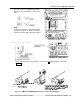
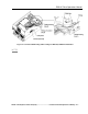
(6) Wiring of the control circuit (40HP/CT, 50HP/VT or greater)
a. Pull out the control circuit wiring along the left panel as shown in Fig. 2-3-11.
b. Secure the cable binding hole A on the left wall of the power terminal block using a cable tie.
Note: The cable tie should not exceed 0.14 ”(3.5mm) in width and 0.06” (1.5mm) in thickness.
c. When an optional PC card is mounted, the signal cables must be secured to cable binding
hole B.