
User Manual


EQ5 AC Drive Operations Manual
_______________________________________________________________________
TECO – Westinghouse Motor Company Trouble Shooting Chart 93
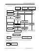
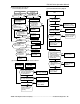
(9) Memory error Er1,
Keypad panel communication error Er2,
CPU error Er3
Er1,2,3 indicated. Abnormal
display or indication goes out.
(10) Output wiring error
Turn the power off then on
again after the CHARGE lamp
(CRG) goes off.
YES
Did the error occur
during tuning?
NO
Is Er7 displayed?
YES
Connect
correctly
or replace
the cable.
Output wiring
error Er7
NO
NO
Are the braking unit and
braking resistor connected
incorrectly?
YES
NO
Is The U,V,W terminal
wiring not connected
or is there an open circuit?
Connect
correctly
or replace
the cable.
Is the keypad panel
connector loose?
Secure
the connector.
NO
YES
Is the operation signal OFF
during auto-tuing?
YES
NO
Is it overcurrent limiting
because of small value of
accelaration/deceleration
time(F07/F08)?
Is the coast-to-stop
signal(BX) ON?
YES
YES
Acceleration/Deceleration
time is longer.
It is OFF.
NO
NO
Is disappeared an
error code on
the LED monitor?
NO
YES
NO
YES
NO
YES
Is the auxiliary
control power input
terminal used?
YES
NO
NO
Is Er1 displayed?
Is it possible to
reset the alarm after
the initialize by H03?
YES
NO
The trouble part is
improvement.
Is there noise
source around?
Inverter is normal.
Continue operation.
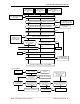
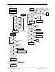
Input phase loss
Lin
NO
NO
NO
YES
YES
Is the setting value of
input phase loss protection
(U48) is correct?
NO
Connect all
three phases.
YES
Is the inverter ROM No.
S09000 or more?
YES
Tightenen the screws
on the terminal block.
Are there loose screws
on the terminal block?
Is there a significant
imbalance voltage
between phases?
NO
YES
Set it correct value.
Is the wiring of CNRXTX(RED)
correct on the power PCB?
(When DC power supply, connect it to the
R0-T0 side and AC power input is
connected to the auxilialy power
input terminal.)
NO
NO
YES
YES
Connect
correctly
the cable.
Are the braking unit and
braking resistor connected
incorrectly?
Connect
correctly
the cable.
YES
(11) Input phase loss
YES
(12) Charging circuit error
Charging circuit error
Er7
Are all main circuit power
supply terminals L1/R, L2/S
and L3/T connected to
the power supply?
Is circuit power supply terminals L1/R, L2/S
and L3/T supplied the power voltage?
NO
Input the voltage.
YES
Did the power off
when the function data
was writing?
Inverter may be faulty.
Contact TWMC.
Faulty inverter or
error due to noise, etc.
Contact TWMC.
Faulty inverter or error
due to noise, etc.
Contact TWMC.
The power supply is incorrect.
The inspection of the power supply
is needed including the wiring.
Faulty inverter or error
due to noise, etc.
Contact TWMC.
Faulty inverter or error
due to noise, etc.
Contact TWMC.
Do not operation signal OFF
until finishing the auto tuning.
Faulty inverter or error
due to noise, etc.
Contact TWMC.
I
s
th
e
U
,
V
,
W
terminal wiring not
connected or is there
an open circuit?
Is the operation signal
OFF during auto-
tunin
g
?
Is it overcurrent limiting
because of small value of
acceleration/deceleration
time (F07/F08)?
(9) Memory error Er1,
Keypad panel communication error Er2,CPU
error Er3
(10) Output wiring error
Is circuit power supply terminals
L1/R,L2/S and L3/T supplied the
power voltage?