H3C AR 18-2X Series Routers Installation Manual Hangzhou H3C Technologies Co., Ltd. http://www.h3c.com Manual Version: T2-08045E-20070423-C-1.
Copyright © 2006-2007, Hangzhou H3C Technologies Co., Ltd. and its licensors All Rights Reserved No part of this manual may be reproduced or transmitted in any form or by any means without prior written consent of Hangzhou H3C Technologies Co., Ltd. Trademarks H3C, , Aolynk, , H3Care, , TOP G, , IRF, NetPilot, Neocean, NeoVTL, SecPro, SecPoint, SecEngine, SecPath, Comware, Secware, Storware, NQA, VVG, V2G, VnG, PSPT, XGbus, N-Bus, TiGem, InnoVision and HUASAN are trademarks of Hangzhou H3C Technologies Co.
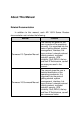
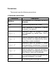
About This Manual Related Documentation In addition to this manual, each AR 18-2X Series Routers documentation set includes the following: Manual Content Comware V3 Operation Manual The manual is a guide for the user to perform the operations correctly.
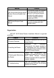
Manual Content Low-End and Mid-Range Series Routers Terminal Access User Manual This manual covers all interface cards and modules available with H3C AR Series Routers, including the cable pinouts, function, interface attribute, panels and LEDs. LMR Series Routers Cable Manual This manual introduces all cable pinouts available with LMR series routers.
Conventions The manual uses the following conventions: I. Command conventions Convention Description Boldface The keywords of a command line are in Boldface. italic Command arguments are in italic. [] Items (keywords or arguments) in square brackets [ ] are optional. { x | y | ... } Alternative items are grouped in braces and separated by vertical bars. One is selected. [ x | y | ... ] Optional alternative items are grouped in square brackets and separated by vertical bars.
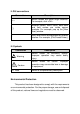
II. GUI conventions Convention Description <> Button names are inside angle brackets. For example, click . [] Window names, menu items, data table and field names are inside square brackets. For example, pop up the [New User] window. / Multi-level menus are separated by forward slashes. For example, [File/Create/Folder]. III. Symbols Convention Warning Caution Note Description Means reader be extremely careful. Improper operation may cause bodily injury. Means reader be careful.
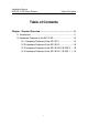
Installation Manual H3C AR 18-2X Series Routers Table of Contents Table of Contents Chapter 1 Product Overview ........................................................1-1 1.1 Introduction ........................................................................1-1 1.2 Hardware Features of the AR 18-2X..................................1-2 1.2.1 Hardware Features of the AR 18-21 .......................1-2 1.2.2 Hardware Features of the AR 18-22 .......................1-6 1.2.
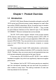
Installation Manual H3C AR 18-2X Series Routers Chapter 1 Product Overview Chapter 1 Product Overview 1.1 Introduction H3C AR 18-2X Series Routers (hereinafter referred to as the AR 18-2X series) are Ethernet access routers designed for small office home office (SOHO) subscribers. By far, the series have six models: AR 18-21/18-22/18-22-8/18-22S-8/18-23-1/18-23S-1. They provide an uplink Ethernet interface and four downlink layer 2 (L2) switched 10/100BASE-T Ethernet interfaces that can be isolated.
Installation Manual H3C AR 18-2X Series Routers Chapter 1 Product Overview 1.2 Hardware Features of the AR 18-2X 1.2.1 Hardware Features of the AR 18-21 I.
Installation Manual H3C AR 18-2X Series Routers Chapter 1 Product Overview II. System specifications Table 1-1 System specifications of the AR 18-21 Item AR 18-21 1 console port Interface 1 x 10/100 Mbps Ethernet interface (WAN) 4 x 10/100 Mbps Ethernet interfaces (LAN) Processor MPC8247 SDRAM 64 MB Flash 8 MB Hardware encryption –– Max. power 10 W Power supply (extern al) Input Output Dimensions (W x D x H) Rated voltage: 100 to 240 VAC; 50 to 60 Hz Current: 0.
Installation Manual H3C AR 18-2X Series Routers Chapter 1 Product Overview III. LEDs You can gather information about the status of the AR 18-21 and its interfaces by reading the seven LEDs on its cover, as shown below. Table 1-2 LEDs on the cover of the AR 18-21 LED LAN1/LAN2/ LAN3/LAN4/ WAN0 Description OFF means no link is present. ON means a link is present. Blinking means data is being sent or/and received. Blinking means the system is operating normally.
Installation Manual H3C AR 18-2X Series Routers Chapter 1 Product Overview Attribute Description Connection to an ASCII terminal Connection to the serial interface on a PC to run the terminal emulation program on the PC Service Command line interface (CLI) 2) Ethernet interface Table 1-4 Attributes of the Ethernet interface Attribute 10BASE-T 10/100BASE-T Connector RJ45 Interface type MDI/MDIX autosensing Operating mode 10 Mbps 10/100 Mbps autosensing Full duplex/half duplex Full duplex/h
Installation Manual H3C AR 18-2X Series Routers Chapter 1 Product Overview 1.2.2 Hardware Features of the AR 18-22 I.
Installation Manual H3C AR 18-2X Series Routers Chapter 1 Product Overview II. System specifications Table 1-5 System specifications of the AR 18-22 Item AR 18-22 1 console port Interface 2 x 10/100 Mbps Ethernet interface (WAN) 4 x 10/100 Mbps Ethernet interfaces (LAN) Processor MPC8247 SDRAM 64 MB Flash 8 MB Hardware encryption –– Max. power 10 W Power supply (extern al) Input Output Dimensions (W x D x H) Rated voltage: 100 to 240 VAC; 50 to 60 Hz Current: 0.
Installation Manual H3C AR 18-2X Series Routers Chapter 1 Product Overview III. LEDs You can gather information about the status of the AR 18-22 and its interfaces by reading the eight LEDs on its cover, as shown below. Table 1-6 LEDs on the cover of the AR 18-22 LED Description OFF means no link is present. LAN1/LAN2/L AN3/LAN4/W AN0/WAN1 ON means a link is present. Blinking means data is being sent or/and received. Blinking means the system is operating normally.
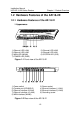
Installation Manual H3C AR 18-2X Series Routers Chapter 1 Product Overview 1.2.3 Hardware Features of the AR 18-22-8/18-22S-8 I.
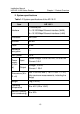
Installation Manual H3C AR 18-2X Series Routers Chapter 1 Product Overview II. System specifications Table 1-7 System specifications of the AR 18-22-8/18-22S-8 Item AR 18-22-8 AR 18-22S-8 1 console port Interface 2 x 10/100 Mbps Ethernet interface (WAN) 8 x 10/100 Mbps Ethernet interfaces (LAN) Processor MPC8248 SDRAM 64 MB 128 MB Flash 8 MB 16 MB Hardware encryption –– Supported Max.
Installation Manual H3C AR 18-2X Series Routers Chapter 1 Product Overview III. LEDs You can gather information about the status of the AR 18-22-8/18-22S-8 and its interfaces by reading the twenty-two LEDs on its cover, as shown below. Every LAN/WAN interface has LEDs LINK/ACT and SPEED to indicate its running state. Table 1-8 LEDs on the cover of the AR 18-22-8/18-22S-8 LED Description OFF means no link is present.
Installation Manual H3C AR 18-2X Series Routers Chapter 1 Product Overview 1.2.4 Hardware Features of the AR 18-23-1/18-23S-1 I.
Installation Manual H3C AR 18-2X Series Routers Chapter 1 Product Overview II. System specifications Table 1-9 System specifications of the AR 18-23-1/18-23S-1 Item AR 18-23-1 AR 18-23S-1 1 console port Interface 4 x 10/100 Mbps Ethernet interface Processor MPC8248 SDRAM 64 MB 128 MB Flash 8 MB 16 MB Hardware encryption –– Supported Max. power 10 W Input voltage and current AC Dimensions (W x D x H) Rated voltage: 100 to 240 VAC; 50 to 60 Hz Current: 0.5 -1 A 300 x 225 x 42 mm (11.
Installation Manual H3C AR 18-2X Series Routers Chapter 1 Product Overview III. LEDs You can gather information about the status of the AR 18-23-1/18-23S-1 and its interfaces by reading the ten LEDs on its cover, as shown below. Table 1-10 LEDs on the cover of the AR 18-23-1/18-23S-1 LED Description OFF means no link is present. ETH0/ ETH1/ ETH2/ ETH3 LINK/ACT Blinking means data is being sent or/and received. SPEED SYS PWR ON means a link is present. OFF means the link rate is 10 Mbps.
Installation Manual H3C AR 18-2X Series Routers Table of Contents Table of Contents Chapter 2 Installing the Router ....................................................2-1 2.1 Safety Precautions .............................................................2-1 2.2 Installing the Router ...........................................................2-2 2.2.1 Placing the Router on a Tabletop/Workbench ........2-2 2.2.2 Mounting the Router on a Vertical Surface .............2-3 2.2.
Installation Manual H3C AR 18-2X Series Routers Chapter 2 Installing the Router Chapter 2 Installing the Router 2.1 Safety Precautions Caution: Observe the safety precautions in this section when installing or maintaining your router to avoid bodily injuries or device impairment caused by improper actions. z Maintain an indoor temperature in the range 0 to 40 C (32 to 104 F) and a humidity level in the range 5 to 90%.
Installation Manual H3C AR 18-2X Series Routers Chapter 2 Installing the Router socket, making sure that the neutral point is well connected to building ground. z Make sure the correct voltage is used. z Put a lightning arrester at the front end of the power input to enhance its lightning protection. To this end, put a special lightning arrester at the front end of signal cables that are led outdoors, such as ISDN, telephone, and T1 cables.
Installation Manual H3C AR 18-2X Series Routers Chapter 2 Installing the Router 2.2.2 Mounting the Router on a Vertical Surface Mount the router on a vertical surface with four pan-head screws and the four brackets at the bottom of the router. Caution: z Securely anchor these four mounting screws in the vertical surface. If the screws are not properly anchored, strain of the network cable connections can pull the router from the wall.
Installation Manual H3C AR 18-2X Series Routers Chapter 2 Installing the Router Figure 2-1 Chassis bottom Step 2: Hang the router on the screws by the four brackets. 2.2.3 Installing the Router in a Rack The AR 18-22-8, AR 18-22S-8, AR 18-23-1, AR 18-23S-1 can be installed in a 19 inch rack. The following are Installation steps. 1) Check the stability and grounding of the rack. Use screws to install rack-mounting ears on the router’s front or rear cover.
Installation Manual H3C AR 18-2X Series Routers 1) Fixing the rack-mounting ears Chapter 2 Installing the Router 2) Fixing the slides Figure 2-2 AR 18-2X installation in a rack 2.3 Connecting the Ground Wire Caution: Properly connect the ground wire before connecting other cables and shorten it as much as possible to prevent the router and the connected device from getting damaged during periods of lightning activities. The grounding screw of the chassis PGND is located on the rear panel.
Installation Manual H3C AR 18-2X Series Routers Chapter 2 Installing the Router 2.4 Connecting the Power Cord I. AC-input power supply For the AR 18-2X series, an external AC-input power supply is provided with these specifications: Input rated voltage: 100 to 240 VAC, 50 to 60 Hz Input current: 0.5 to 1A Output voltage: 12 VDC Output current: 1.25 A Figure 2-3 illustrates the power supply: Figure 2-3 Power supply II.
Installation Manual H3C AR 18-2X Series Routers Chapter 2 Installing the Router Step 4: Check that the PWR LED on the front panel of the router is ON. If the LED is OFF, repeat steps 2 through 4. Caution: If the PWR LED is still off after you repeat steps 2 through 4 several times, refer to “Chapter 4 Troubleshooting” for a solution. 2.5 Connecting the Router to a Console Terminal I. Console cable The console cable has an RJ45 connector at one end and a DB9 (female) connector at the other end.
Installation Manual H3C AR 18-2X Series Routers Chapter 2 Installing the Router Step 2: Connect the console cable. Power off the router and the console terminal, and then connect the RS-232 serial port on the console terminal to the console port on the router using the console cable. Verify the connection and power on the router. In normal cases, the startup information is displayed on the terminal screen. For details, refer to “Chapter 3 Starting and Maintaining the Router”. 2.
Installation Manual H3C AR 18-2X Series Routers Chapter 2 Installing the Router cable is used for connecting the same type of devices, such as PC to PC or PC to router. Caution: In preparing network cables, shielded cables are preferred for the sake of electromagnetic compatibility. II. Connecting an Ethernet cable Caution: Read the mark above the port to be connected carefully before making connection to make sure it is the right port.
Installation Manual H3C AR 18-2X Series Routers Chapter 2 Installing the Router z The proper power supply is used. z The grounding wire of the router is correctly connected. z The console cable and the power cord are correctly connected.
Installation Manual H3C AR 18-2X Series Routers Table of Contents Table of Contents Chapter 3 Starting and Maintaining the Router..........................3-1 3.1 Starting up the Router........................................................3-1 3.1.1 Setting up a Configuration Environment .................3-1 3.1.2 Powering on the Router...........................................3-5 3.2 Maintaining the Router.......................................................3-6 3.2.
Installation Manual H3C AR 18-2X Series Routers Chapter 3 Starting and Maintaining the Router Chapter 3 Starting and Maintaining the Router 3.1 Starting up the Router 3.1.1 Setting up a Configuration Environment I. Connecting the router to a console terminal To set up a local configuration environment, simply connect the RJ45 connector of the console cable to the console port on the router, and the DB9 connector to the serial port on the console terminal, a PC for example, as shown in Figure 3-1.
Installation Manual H3C AR 18-2X Series Routers Chapter 3 Starting and Maintaining the Router The HyperTerminal window displays the Connection Description dialog box, as shown in Figure 3-2. Figure 3-2 Setting up a new connection Step 2: Enter the name of the new connection in the Name field and click . The dialog box, as shown in Figure 3-3, displays. Step 3: Select the serial port to be used from the Connect Using dropdown menu. The serial port must be the same port connected by the console cable.
Installation Manual H3C AR 18-2X Series Routers Chapter 3 Starting and Maintaining the Router Figure 3-3 Setting the connection port Step 4: Click . The Port Settings tab, shown in Figure 3-4, appears and you can set serial port parameters.
Installation Manual H3C AR 18-2X Series Routers Chapter 3 Starting and Maintaining the Router Figure 3-4 Setting communications parameters Step 6: Click . The HyperTerminal dialogue box appears. Step 7: Select Properties. Step 8: In the Properties dialog box, select the Settings tab, as shown in Figure 3-5. Step 9: Select VT100 or Auto detect in the Emulation dropdown menu. Step 10: Click .
Installation Manual H3C AR 18-2X Series Routers Chapter 3 Starting and Maintaining the Router Figure 3-5 Setting the terminal type 3.1.2 Powering on the Router After the router is powered on, the Boot Rom program runs first and the following system information appears on the terminal screen: System starts booting...(V10.
Installation Manual H3C AR 18-2X Series Routers * Chapter 3 Starting and Maintaining the Router H3C Series Routers Boot Rom V15.00 * * * ************************************************** Copyright(c) 2004-2006 Hangzhou H3C Tech. Co., Ltd. Compiled at Tue Mar 28 14:58:33 CST 2006 Testing memory...OK! 256M bytes DDR SDRAM Memory 16M bytes Flash Memory Hardware Version is 4.0 CPLD Version is 1.0 Press Ctrl-B to enter Boot Menu Press .
Installation Manual H3C AR 18-2X Series Routers Please Chapter 3 Starting and Maintaining the Router input Boot Rom password : Caution: z Press within three seconds after the prompt “Press Ctrl-B to Enter Boot Menu...?” appears to enter the Boot Menu. Otherwise, the system starts decompressing the program. z If you want to enter the Boot menu after the system starts decompressing the program, you need to reboot the router. Type the correct password and press .
Installation Manual H3C AR 18-2X Series Routers 2) Chapter 3 Starting and Maintaining the Router To download an application program through Ethernet, select <2>. This menu appears: Net Port Download Menu: 1: Change Net Parameter 2: Download From Net 3: Exit to Main Menu Enter your choice(1-3):1 z Select <1> to change the parameters for downloading. The following information is displayed: Change Boot Parameter: '.
Installation Manual H3C AR 18-2X Series Routers Chapter 3 Starting and Maintaining the Router Note: You can change the parameter settings behind the colons (:). The “boot device” field is “motfcc1” for AR 18-2X routers. The AR 18-2X allows you to download programs through both TFTP and FTP. For the procedures, see the section 3.2.5 "Upgrading Boot ROM at CLI". After you set the parameters, select <2> to start z downloading. z Select <3> to exit to the main menu.
Installation Manual H3C AR 18-2X Series Routers Chapter 3 Starting and Maintaining the Router 3: Restore Extended Segment of Boot Rom from FLASH 4: Backup Extended Segment of Boot Rom to FLASH 5: Exit to Main Menu Enter your choice(1-5): The menu provides approaches to Boot Rom upgrade, backup, and recovery. See the sections “3.2.3 Upgrading Programs through XModem” and “3.2.4 Backing up and Restoring the Extended Segment of the Boot Rom Program” for the procedures.
Installation Manual H3C AR 18-2X Series Routers Chapter 3 Starting and Maintaining the Router Caution: z Press within three seconds after the prompt “Press Ctrl-B to Enter Boot Menu...?” appears to enter the Boot Menu. Otherwise, the system starts decompressing the program. z If you want to enter the Boot menu after the system starts decompressing the program, you need to reboot the router. Type the correct password and press .
Installation Manual H3C AR 18-2X Series Routers 2) Chapter 3 Starting and Maintaining the Router Download an application through Ethernet. After you select this option, the screen displays this menu: Net Port Download Menu: 1: Change Net Parameter 2: Download From Net 3: Exit to Main Menu Enter your choice(1-3):1 3) Set the type of the application file used at startup The dual image function is available with the router when it is installed with a 16 MB or larger Flash.
Installation Manual H3C AR 18-2X Series Routers Chapter 3 Starting and Maintaining the Router M+B (that is, both of type M and B) file exists, it is impossible to have another M or B file. If you change the file type of another file to B, the M+B file becomes a type M file. z You can modify the file name of an application image in Flash memory using the command after it boots. For more information, refer to Comware V3 Operation Manual – System Management.
Installation Manual H3C AR 18-2X Series Routers Chapter 3 Starting and Maintaining the Router Select option 2. The system enters the following menu, where you can change the file type of backup.bin. Set this file as: 1. Main 2. Backup 3. Exit Enter your choice(1-3): 1 Select option 1 for example to specify the backup.bin file as the main boot file. After the modification takes effect, the file type of the original main file named main.bin changes to N/A, while the file type of the backup.
Installation Manual H3C AR 18-2X Series Routers 6) Chapter 3 Starting and Maintaining the Router Start up with the initial configuration, ignoring the configuration file. In case the password is lost, you can use this option to ignore the existing configuration and access the router with the initial configuration. Then you can change the password. To have the router start up with the new configuration file at next boot, however, you must save the configuration after you change the password.
Installation Manual H3C AR 18-2X Series Routers Chapter 3 Starting and Maintaining the Router 3.2.3 Upgrading Programs through XModem When you upgrade software through XModem, you can do that using the console port without having to set up another configuration environment. I. Upgrading an application program Step 1: Enter the Boot menu and press <1> to download an application program using XModem. The following download speeds are available for the router: Downloading application program from serial ...
Installation Manual H3C AR 18-2X Series Routers Chapter 3 Starting and Maintaining the Router Downloading ... CCCCC Note: The new baud rate takes effect only after you reconnect the terminal emulation program. Step 4: Select [Transmit/send file] in the terminal window. The following dialog box pops up: Figure 3-6 Send File dialog box Step 5: Click . Select the application file to be downloaded and set protocol to XModem. Click .
Installation Manual H3C AR 18-2X Series Routers Chapter 3 Starting and Maintaining the Router Figure 3-7 Sending file interface Step 6: After completing downloading, the system begins writing data to the Flash, and then displays the following information in the terminal interface, indicating completion of the downloading: Download completed. Writing to flash memory... Please wait,it needs a long time .Please wait... ####################################################### Writing FLASH Success.
Installation Manual H3C AR 18-2X Series Routers Chapter 3 Starting and Maintaining the Router II. Upgrading the Boot Rom program Step 1: Enter the Boot Menu, and then select <7> to enter the Boot Rom operation sub-menu. Step 2: Enter <1> in the Boot Rom operation sub-menu to upgrade the Boot Rom program using XModem. Several speed options are available for you. The subsequent steps are the same as those described in “I. Upgrading an application program” of this section.
Installation Manual H3C AR 18-2X Series Routers Chapter 3 Starting and Maintaining the Router Step 2: Select <2> in the operation sub-menu to upgrade the extended segment of the Boot Rom program using XModem. Several speed options are available for you. The subsequent steps are the same as those described in "I. Upgrading an application program” of this section. Caution: This upgrade approach is only used to upgrade a portion of the Boot Rom program, so you can make a second attempt once errors occur.
Installation Manual H3C AR 18-2X Series Routers Chapter 3 Starting and Maintaining the Router Backuping Boot ROM program to FLASH successed! Step 3: When the sub-menu appears again, select <5> to exit and reboot the router. II.
Installation Manual H3C AR 18-2X Series Routers Chapter 3 Starting and Maintaining the Router other. A TFTP server is a device running the TFTP server program. 2) Specify the path on the TFTP server to the folder that contains the Boot ROM upgrade file. That is, ensure the Boot ROM upgrade file are available in the Base Directory folder, as shown in Figure 3-8 (For different TFTP server software packages, the interfaces differ).
Installation Manual H3C AR 18-2X Series Routers Chapter 3 Starting and Maintaining the Router As shown in the above display, 1.1.1.1 is the IP address of the TFTP server, and bootromfull is the Boot ROM upgrade file. 4) Execute the following command on the router to upgrade Boot ROM. system-view [H3C] upgrade bootrom full WARNING: This operation will update the Boot ROM. It may result in booting failure.
Installation Manual H3C AR 18-2X Series Routers Chapter 3 Starting and Maintaining the Router file. (For different FTP server software packages, the interfaces differ). Figure 3-9 FTP server program interface 3) Configure the router to download the Boot ROM upgrade file from the FTP server. ftp 1.1.1.1 Trying 1.1.1.1 ... Press CTRL+K to abort Connected to 1.1.1.1. 220 3Com 3CDaemon FTP Server Version 2.0 User(1.1.1.1:(none)):guest //Enter the username configured on the FTP server.
Installation Manual H3C AR 18-2X Series Routers Chapter 3 Starting and Maintaining the Router successfully. [ftp] get bootromfull 4) Execute the following command on the router to upgrade Boot ROM. system-view [H3C] upgrade bootrom full WARNING: This operation will update the Boot ROM. It may result in booting failure.
Installation Manual H3C AR 18-2X Series Routers Chapter 3 Starting and Maintaining the Router Caution: The AR 18-2X series does not provide any TFTP or FTP server program. You need to purchase and install one by yourself. Follow these steps to upgrade an application program through TFTP or FTP: 1) Start the TFTP or FTP server Start the TFTP or FTP server on the PC connected to the Ethernet interface on the router and set the path to the file that is to be downloaded.
Installation Manual H3C AR 18-2X Series Routers Chapter 3 Starting and Maintaining the Router inet on ethernet (e): IP address of the interface used for downloading on the router host inet (h): IP address of the FTP server user (u): username, same as the one configured on the FTP server ftp password (pw) (blank = use rsh): password, same as the one configured on the FTP server flags (f): set to 0x0 These values are automatically saved after you configure them. 4) Press .
Installation Manual H3C AR 18-2X Series Routers Chapter 3 Starting and Maintaining the Router Please wait,it needs a long time ####################################################### ########################### Writing Comwaresoftware File Succeeds! Press key to reboot the system . Press as prompted to have the router reboot.
Installation Manual H3C AR 18-2X Series Routers Table of Contents Table of Contents Chapter 4 Troubleshooting...........................................................4-1 4.1 Troubleshooting the Power System ...................................4-1 4.2 Troubleshooting the Configuration System........................4-1 4.3 Recovering/Replacing a Lost Boot Rom Password ...........
Installation Manual H3C AR 18-2X Series Routers Chapter 4 Troubleshooting Chapter 4 Troubleshooting 4.1 Troubleshooting the Power System Symptoms: POWER LED cannot light. Solution: Check that: z The power switch of the router is turned on. z The switch of the power source is turned on. z The power cord of the router is properly connected. z The correct power source is used. Caution: Do not plug/unplug the power cord when power is being supplied.
Installation Manual H3C AR 18-2X Series Routers Chapter 4 Troubleshooting Symptoms 1: Nothing is displayed on the terminal screen after the router is powered on. Solution: Step 1: Check that: z The power system is correctly working. z The console cable is connected correctly. Step 2: Check the console cable and the terminal (such as the HyperTerminal) parameter settings. Symptoms 2: Illegible characters are displayed on the console terminal after the router is powered on.
Installation Manual H3C AR 18-2X Series Routers Chapter 4 Troubleshooting 4.3 Recovering/Replacing a Lost Boot Rom Password If the Boot Rom password of the router is lost, contact the local agent of H3C for help.