HP ProLiant BL465c G7 Server Blade Maintenance and Service Guide Part Number 594690-001 June 2010 (First Edition)
© Copyright 2010 Hewlett-Packard Development Company, L.P. The information contained herein is subject to change without notice. The only warranties for HP products and services are set forth in the express warranty statements accompanying such products and services. Nothing herein should be construed as constituting an additional warranty. HP shall not be liable for technical or editorial errors or omissions contained herein. Microsoft and Windows are U.S. registered trademarks of Microsoft Corporation.
Contents Customer self repair ...................................................................................................................... 5 Parts only warranty service ............................................................................................................................ 5 Illustrated parts catalog ............................................................................................................... 16 Server blade components ........................................
External USB functionality ................................................................................................................. 50 Internal SD support ..................................................................................................................................... 50 Component identification ............................................................................................................. 51 Front panel components .................................................
Customer self repair HP products are designed with many Customer Self Repair (CSR) parts to minimize repair time and allow for greater flexibility in performing defective parts replacement. If during the diagnosis period HP (or HP service providers or service partners) identifies that the repair can be accomplished by the use of a CSR part, HP will ship that part directly to you for replacement. There are two categories of CSR parts: • Mandatory—Parts for which customer self repair is mandatory.
Obligatoire - Pièces pour lesquelles la réparation par le client est obligatoire. Si vous demandez à HP de remplacer ces pièces, les coûts de déplacement et main d'œuvre du service vous seront facturés. Facultatif - Pièces pour lesquelles la réparation par le client est facultative. Ces pièces sont également conçues pour permettre au client d'effectuer lui-même la réparation.
NOTA: alcuni componenti HP non sono progettati per la riparazione da parte del cliente. Per rispettare la garanzia, HP richiede che queste parti siano sostituite da un centro di assistenza autorizzato. Tali parti sono identificate da un "No" nel Catalogo illustrato dei componenti. In base alla disponibilità e alla località geografica, le parti CSR vengono spedite con consegna entro il giorno lavorativo seguente.
anrufen und sich von einem Mitarbeiter per Telefon helfen lassen. Den Materialien, die mit einem CSRErsatzteil geliefert werden, können Sie entnehmen, ob das defekte Teil an HP zurückgeschickt werden muss. Wenn es erforderlich ist, das defekte Teil an HP zurückzuschicken, müssen Sie dies innerhalb eines vorgegebenen Zeitraums tun, in der Regel innerhalb von fünf (5) Geschäftstagen.
Centro de asistencia técnica de HP y recibirá ayuda telefónica por parte de un técnico. Con el envío de materiales para la sustitución de componentes CSR, HP especificará si los componentes defectuosos deberán devolverse a HP. En aquellos casos en los que sea necesario devolver algún componente a HP, deberá hacerlo en el periodo de tiempo especificado, normalmente cinco días laborables. Los componentes defectuosos deberán devolverse con toda la documentación relacionada y con el embalaje de envío.
bijbehorende documentatie worden geretourneerd in het meegeleverde verpakkingsmateriaal. Als u het defecte onderdeel niet terugzendt, kan HP u voor het vervangende onderdeel kosten in rekening brengen. Bij reparatie door de klant betaalt HP alle verzendkosten voor het vervangende en geretourneerde onderdeel en kiest HP zelf welke koerier/transportonderneming hiervoor wordt gebruikt. Neem contact op met een Service Partner voor meer informatie over het Customer Self Repair programma van HP.
Serviço de garantia apenas para peças A garantia limitada da HP pode incluir um serviço de garantia apenas para peças. Segundo os termos do serviço de garantia apenas para peças, a HP fornece as peças de reposição sem cobrar nenhuma taxa. No caso desse serviço, a substituição de peças CSR é obrigatória. Se desejar que a HP substitua essas peças, serão cobradas as despesas de transporte e mão-de-obra do serviço.
Customer self repair 12
Customer self repair 13
Customer self repair 14
Customer self repair 15
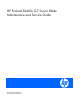
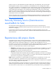
Illustrated parts catalog Server blade components Customer self repair (on page 5) Item Description Spare part number 1 System board assembly 598247-001 Mandatory1 2 DIMMs — — a) 8-GB, dual-rank, PC3-10600, registered 595097-001 Mandatory1 b) 4-GB, dual-rank, PC3-10600, registered* 595096-001 Mandatory1 c) 2-GB, dual-rank, PC3-10600, registered* 595094-001 Mandatory1 d) 4-GB, single-rank, PC3-10600, unbuffered* 595102-001 Mandatory1 e) 2-GB, dual-rank, PC3-10600, unbuffered* 595101
a) Processor 1 598248-001 Optional2 b) Processor 2* 598249-001 Optional2 Processors — — a) 2.4-GHz AMD Opteron™ Model 6136** 583753-001 Optional2 b) 2.3-GHz AMD Opteron™ Model 6134* ** 583752-001 Optional2 c) 2.2-GHz AMD Opteron™ Model 6174* ** 598729-001 Optional2 d) 2.1-GHz AMD Opteron™ Model 6172* ** 583755-001 Optional2 e) 1.7-GHz AMD Opteron™ Model 6164HE* ** 598730-001 Optional2 f) 2.
15 16 17 18 b) QLogic QMH2462 4Gb FC HBA for HP c-Class BladeSystem* 405920-001 Mandatory1 c) Emulex LPe1205-HP 8Gb FC HBA for HP c-Class BladeSystem* 456978-001 Mandatory1 d) QLogic QMH2562 8Gb FC HBA for HP c-Class BladeSystem* 455869-001 Mandatory1 Ethernet mezzanine card options — — a) HP NC325m PCI Express Quad Port Gigabit Server Adapter for c-Class BladeSystem* 436011-001 Mandatory1 b) HP NC326m PCI Express Dual Port 1Gb Server Adapter for c-Class BladeSystem* 419330-001 Mandator
*Not shown **Do not mix processors with different model numbers, speeds, cache sizes, or power consumption. 1 Mandatory—Parts for which customer self repair is mandatory. If you request HP to replace these parts, you will be charged for the travel and labor costs of this service. 2 Optional—Parts for which customer self repair is optional. These parts are also designed for customer self repair.
No: Nee—Sommige HP onderdelen zijn niet ontwikkeld voor reparatie door de klant. In verband met de garantievoorwaarden moet het onderdeel door een geautoriseerde Service Partner worden vervangen. Deze onderdelen worden in de geïllustreerde onderdelencatalogus aangemerkt met "Nee". 3 Mandatory: Obrigatória—Peças cujo reparo feito pelo cliente é obrigatório. Se desejar que a HP substitua essas peças, serão cobradas as despesas de transporte e mão-de-obra do serviço.
Removal and replacement procedures Required tools You need the following items for some procedures: • T-15 Torx screwdriver (provided inside the access panel) • HP Insight Diagnostics software ("HP Insight Diagnostics" on page 48) Safety considerations Before performing service procedures, review all the safety information. Preventing electrostatic discharge To prevent damaging the system, be aware of the precautions you need to follow when setting up the system or handling parts.
Symbols on equipment The following symbols may be placed on equipment to indicate the presence of potentially hazardous conditions. This symbol indicates the presence of hazardous energy circuits or electric shock hazards. Refer all servicing to qualified personnel. WARNING: To reduce the risk of injury from electric shock hazards, do not open this enclosure. Refer all maintenance, upgrades, and servicing to qualified personnel. This symbol indicates the presence of electric shock hazards.
This method initiates a controlled remote shutdown of applications and the OS before the server blade enter standby mode. • Press and release the Power On/Standby button. This method initiates a controlled shutdown of applications and the OS before the server blade enter standby mode. • Press and hold the Power On/Standby button for more than 4 seconds to force the server blade to enter standby mode.
3. Remove the server blade. 4. Place the server blade on a flat, level work surface. WARNING: To reduce the risk of personal injury from hot surfaces, allow the drives and the internal system components to cool before touching them. CAUTION: To prevent damage to electrical components, properly ground the server blade before beginning any installation procedure. Improper grounding can cause ESD. Access panel To remove the component: 1. Power down the server blade (on page 22). 2.
Hard drive blank CAUTION: To prevent improper cooling and thermal damage, do not operate the server blade or the enclosure unless all hard drive and device bays are populated with either a component or a blank. Remove the component as indicated. To replace the blank, slide the blank into the bay until it locks into place. Hard drive To remove the component: 1. Determine the status of the hard drive from the hot-plug SAS hard drive LED combinations ("SAS and SATA hard drive LED combinations" on page 52).
b. Release the hard drive tray, slide it forward until it locks, and then press hard drive carrier 1 down to access hard drive 2. c. Remove hard drive 2. To replace the component, reverse the removal procedure. DIMM baffle CAUTION: To avoid damage to the server blade and the enclosure, install all DIMM baffles in the proper location after adding or replacing DIMMs. DIMM baffles that are missing or installed incorrectly can compromise server blade and enclosure cooling. To remove the component: 1.
3. Remove the access panel ("Access panel" on page 24). 4. Disconnect the cables, and then remove the DIMM baffle. To replace the component, reverse the removal procedure. DIMMs To remove the component: 1. Power down the server blade (on page 22). 2. Remove the server blade (on page 23). 3. Remove the access panel ("Access panel" on page 24). 4. Remove the DIMM baffle ("DIMM baffle" on page 26). 5. Remove the DIMM. To replace the component, reverse the removal procedure.
HP Smart Array Controller To remove the component: 1. Power down the server blade (on page 22). 2. Remove the server blade (on page 23). 3. Remove the access panel ("Access panel" on page 24). 4. Disconnect the cables, and then remove the DIMM baffle. 5. Remove the HP Smart Array Controller. To replace the component, reverse the removal procedure.
Mezzanine card Optional mezzanine cards enable network connectivity or provide Fibre Channel support. For mezzanine card locations, see the system board components (on page 53). Because mezzanine cards are supported on multiple server blade models, the mezzanine card may have captive screws that are not required to secure it to the server blade. When installing a mezzanine card in this server blade, only two captive screws are required. To remove the component: 1. Power down the server blade (on page 22).
1. Install the mezzanine card. Press down on the connector to seat the board. 2. Install the access panel ("Access panel" on page 24). Cache module capacitor pack To remove the component: 1. Power down the server blade (on page 22). 2. Remove the server blade (on page 23). 3. Remove the access panel ("Access panel" on page 24). 4. Remove the cache module capacitor pack. IMPORTANT: The spare capacitor pack ships with two small feet installed.
Front panel/hard drive cage assembly To remove the component: 1. Power down the server blade (on page 22). 2. Remove the server blade (on page 23). 3. Remove the access panel ("Access panel" on page 24). 4. Remove all hard drive blanks ("Hard drive blank" on page 25). 5. Remove all hard drives ("Hard drive" on page 25). 6. Disconnect the SAS/SATA cables and power cable from the hard drive backplane, and then remove the front panel/hard drive cage assembly.
7. Remove the heatsink. To replace the component: 1. Clean the old thermal grease from the processor with the alcohol swab. Allow the alcohol to evaporate before continuing. CAUTION: The heatsink thermal interface media is not reusable and must be replaced if the heatsink is removed from the processor after it has been installed. 2. Apply all the grease to the top of the processor in one of the following patterns to ensure even distribution.
3. Remove the thermal interface media protective cover. 4. Align and install the heatsink. Alternate tightening the screws until the heatsink is seated properly. 5. Install the access panel ("Access panel" on page 24). Processor WARNING: To reduce the risk of personal injury from hot surfaces, allow the drives and the internal system components to cool before touching them. CAUTION: To prevent possible server malfunction, do not mix processors of different speeds or cache sizes.
IMPORTANT: Processor socket 1 must always be populated. If processor socket 1 is empty, the server blade does not power up. To remove the component: 1. Power down the server blade (on page 22). 2. Remove the server blade (on page 23). 3. Remove all hard drive blanks ("Hard drive blank" on page 25). 4. Remove all hard drives ("Hard drive" on page 25). 5. Remove the access panel ("Access panel" on page 24). 6.
9. Using your fingers, remove the failed processor. To replace the component: CAUTION: The pins on the processor socket are very fragile. Any damage to them may require replacing the system board. CAUTION: Failure to completely open the processor locking lever prevents the processor from seating during installation, leading to hardware damage. IMPORTANT: Be sure the processor remains inside the processor installation tool. 1.
CAUTION: The processor is designed to fit one way into the socket. Use the alignment guides on the processor and socket to properly align the processor with the socket. 3. Press down firmly until the processor installation tool clicks and separates from the processor, and then remove the processor installation tool.
4. Close the processor retaining bracket and the processor retaining latch. 5. Clean the old thermal grease from the heatsink with the alcohol swab. Allow the alcohol to evaporate before continuing. 6. Apply all the grease to the top of the processor in one of the following patterns to ensure even distribution. CAUTION: The heatsink thermal interface media is not reusable and must be replaced if the heatsink is removed from the processor after it has been installed.
7. Align and install the heatsink. Alternate tightening the screws until the heatsink is seated properly. 8. Install the access panel ("Access panel" on page 24). System board To remove the component: 1. Power down the server blade (on page 22). 2. Remove the server blade (on page 23). 3. Remove the access panel ("Access panel" on page 24). 4. Remove all hard drive blanks ("Hard drive blank" on page 25). 5. Remove all hard drives ("Hard drive" on page 25). 6.
12. Open the processor retaining latch and the processor socket retaining bracket. 13. Using the tool, remove the processor from the failed system board. CAUTION: To avoid damage to the system board: • Do not touch the processor socket contacts. • Always install the processor socket cover after removing the processor from the socket. • Do not tilt or slide the processor when lowering the processor into the socket. CAUTION: To avoid damage to the processor: • Handle the processor only by the edges.
1. Remove the processor socket protective cover. 2. Install the processor socket cover onto the processor socket of the failed system board. 3. Install the processor on the spare system board. CAUTION: The processor is designed to fit one way into the socket. Use the alignment guides on the processor and socket to properly align the processor with the socket. CAUTION: Always install the processor parallel to the system board to avoid damage to the pins.
4. Close the processor retaining latch and the processor socket retaining bracket. 5. Clean the old thermal grease from the heatsink and the top of the processor with the alcohol swab. Allow the alcohol to evaporate before continuing. 6. Apply all the grease to the top of the processor in one of the following patterns to ensure even distribution. CAUTION: The heatsink thermal interface media is not reusable and must be replaced if the heatsink is removed from the processor after it has been installed.
10. Install the hard drives ("Hard drive" on page 25). IMPORTANT: To avoid damage to the server blade, support the riser board when installing the TPM board and rivet. 11. If necessary, install the TPM module. For more information, see the HP ProLiant BL465c G7 Server Blade User Guide. 12. Install the access panel ("Access panel" on page 24). After you replace the system board, you must re-enter the server blade serial number and the product ID. 1.
WARNING: The computer contains an internal lithium manganese dioxide, a vanadium pentoxide, or an alkaline battery pack. A risk of fire and burns exists if the battery pack is not properly handled. To reduce the risk of personal injury: • Do not attempt to recharge the battery. • Do not expose the battery to temperatures higher than 60°C (140°F). • Do not disassemble, crush, puncture, short external contacts, or dispose of in fire or water. • Replace only with the spare designated for this product.
Cabling Hard drive power cabling Hot-plug SAS/SATA hard drive cabling Cabling 44
Cache module capacitor pack cabling Using the HP c-Class Blade SUV Cable The HP c-Class Blade SUV Cable enables the user to perform server blade administration, configuration, and diagnostic procedures by connecting video and USB devices directly to the server blade. For SUV cable connectors, see "HP c-Class Blade SUV Cable (on page 56).
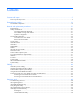
2. Connect the video connector to a monitor. 3. Connect a USB mouse to one USB connector. 4. Connect a USB keyboard to the second USB connector. Item Description 1 Monitor 2 USB mouse 3 USB keyboard 4 HP c-Class Blade SUV Cable Accessing a server blade with local media devices Use the following configuration when configuring a server blade or loading software updates and patches from a USB CD/DVD-ROM or a USB diskette. 1. Connect the local I/O cable to the server blade. 2.
Item Description 1 Monitor 2 USB CD/DVD-ROM drive or diskette drive 3 USB keyboard 4 USB hub 5 USB mouse 6 Local I/O cable Cabling 47
Diagnostic tools Troubleshooting resources The HP ProLiant Servers Troubleshooting Guide provides procedures for resolving common problems and comprehensive courses of action for fault isolation and identification, error message interpretation, issue resolution, and software maintenance on ProLiant servers and server blades. This guide includes problemspecific flowcharts to help you navigate complex troubleshooting processes. To view the guide, select a language: • English (http://www.hp.
• From within HP SIM • From within operating system-specific IML viewers: o For Windows®: IML Viewer o For Linux: IML Viewer Application • From within the iLO 3 user interface • From within HP Insight Diagnostics (on page 48) • From within the Onboard Administrator GUI For more information, see the HP BladeSystem Onboard Administrator User Guide on the HP website (http://www.hp.com/go/bladesystem/documentation).
Both HP Insight Remote Support solutions are available at no additional cost to customers with a valid warranty on HP technology, an HP Care Pack Service or HP contractual support agreement. For more information, see the HP website (http://www.hp.com/go/insightremotesupport). USB support and functionality USB support HP provides both standard USB 2.0 support and legacy USB 2.0 support. Standard support is provided by the OS through the appropriate USB device drivers.
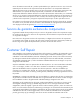
Component identification Front panel components Item Description 1 Serial label pull tab 2 SUV connector* 3 Server blade release button 4 Power On/Standby button 5 Server blade release lever 6 Hard drive bays * The SUV connector and the HP c-Class Blade SUV cable are for some server blade configuration and diagnostic procedures.
Item Description Status Off = No link or activity 4 Flex 2 LED* Green = Network linked Green flashing = Network activity Off = No link or activity 5 System power LED Green = On Amber = Standby (auxiliary power available) Off = Off * Actual NIC numbers depend on several factors, including the operating system installed on the server blade.
Online/activity LED (green) Fault/UID LED (amber/blue) Interpretation Flashing regularly (1 Hz) Amber, flashing regularly (1 Hz) Do not remove the drive. Removing a drive may terminate the current operation and cause data loss. The drive is part of an array that is undergoing capacity expansion or stripe migration, but a predictive failure alert has been received for this drive. To minimize the risk of data loss, do not replace the drive until the expansion or migration is complete.
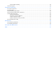
Item Description 1 DIMM slots (Processor 2) 2 DIMM slots (Processor 1) 3 Smart Array connector 4 TPM security rivet (optional) 5 Micro SD connnector 6 Internal USB connector 7 Mezzanine connector 2 (Type I or Type II mezzanine) 8 Enclosure connector 9 Mezzanine connector 1 (Type I mezzanine only) 10 System maintenance switch (SW1) 11 Embedded NICs (2) 12 Battery 13 Processor socket 1 (populated) 14 Processor socket 2 The symbols correspond to the symbols located on the intercon
Item PCIe Mezzanine connector 2 x8, Type I or II mezzanine card A PCIe x4 mezzanine connector supports x8 cards at up to x4 speeds. A PCIe x8 mezzanine connector supports x16 cards at up to x8 speeds.
9. Change position 6 of the system maintenance switch to off. 10. Repeat steps 5 and 6. IMPORTANT: When the server blade boots after NVRAM is cleared, a delay of up to 2 minutes is normal. During this delay, the system appears non-functional. Do not attempt any procedures during the delay. Accessing the redundant ROM If the system ROM is corrupted, the system automatically switches to the redundant ROM in most cases.
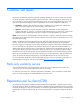
Item Connector Description 2 Video For connecting a video monitor 3 USB For connecting up to two USB devices 4 Serial For trained personnel to connect a null modem serial cable and perform advanced diagnostic procedures Component identification 57
Specifications Environmental specifications Specification Value — Temperature range* Operating 10°C to 35°C (50°F to 95°F) Non-operating -30°C to 60°C (-22°F to 140°F) Relative humidity (noncondensing)** — Operating 10% to 90% @ 28°C (82.4°F) Non-operating 5% to 95% @ 38.7°C (101.7°F) Altitude† — Operating 3050 m (10,000 ft) Non-operating 9144 m (30,000 ft) * The following temperature conditions and limitations apply: - All temperature ratings shown are for sea level.
Acronyms and abbreviations ADU Array Diagnostics Utility CSR Customer Self Repair ESD electrostatic discharge iLO 3 Integrated Lights-Out 3 IML Integrated Management Log ORCA Option ROM Configuration for Arrays POST Power-On Self Test PSP ProLiant Support Pack PXE Preboot Execution Environment RBSU ROM-Based Setup Utility SAS serial attached SCSI SATA serial ATA Acronyms and abbreviations 59
SD Secure Digital SIM Systems Insight Manager SMP Server Migration Pack TPM trusted platform module UID unit identification USB universal serial bus Acronyms and abbreviations 60
Index A H access panel 24 accessing a server blade with local KVM 45, 46 ADU (Array Diagnostic Utility) 49 hard drive blanks 25 hard drive cabling 44 hard drive LEDs 52 hard drive power cable 44 hard drives 25, 52 hard drives, determining status of 52 health LEDs 52 heatsink 31 Hot-plug SAS/SATA hard drive cabling 44 HP Insight Diagnostics 21, 48 HP Insight Remote Support software 49 HP Smart Array controller 28 B batteries, replacing 42 battery 42 buttons 51 C cables 44, 45 cabling 44, 45 cache module
R removing the access panel 24 removing the server blade 23 resources 48 resources, troubleshooting 48 ROM redundancy 56 S safety considerations 21 safety information 21 SAS cabling 44 SAS drives 52 SAS hard drive LEDs 52 SATA hard drive 52 SATA hard drive LEDs 52 serial connector 56 specifications 58 static electricity 21 SUV cable 56 symbols on equipment 22 system board 38 system board components 53, 54, 55, 56 system maintenance switch 55 system maintenance switch procedures 55 T TPM (Trusted Platform