H Broadband Service Analyzer Setting Up the 25.
Copyright Notice Warranty Printing history © Hewlett-Packard Australia Ltd 1997 All rights reserved. The information contained in this document is subject to change without notice. TO THE EXTENT ALLOWED BY LOCAL LAW, HEWLETT-PACKARD MAKES NO WARRANTY OF ANY KIND WITH REGARD TO THIS MATERIAL, INCLUDING, BUT NOT LIMITED TO, THE IMPLIED WARRANTIES OF MERCHANTABILITY AND FITNESS FOR A PARTICULAR PURPOSE.
Contents Guide to the Broadband Service Analyzer Documentation ..........................iv About the 25.6 Mb/s Interface Pod ................................................................ 1 Online Help ..................................................................................................... 2 To Access User Online Help...................................................................... 2 Front Panel at a Glance ................................................................................
Guide to the HP E5200A Broadband Service Analyzer Documentation Guide to the HP E5200A Broadband Service Analyzer Documentation The HP E5200A Broadband Service Analyzer comes with a comprehensive set of paper and online documentation. Use the following table to determine which documents you should use.
About the 25.6 Mb/s Interface Pod About the 25.6 Mb/s Interface Pod Overview The HP E5129A 25.6 Mb/s Interface Pod is a self-contained, plug-in module. You use it in conjunction with the HP E5200A Broadband Service Analyzer to test and analyze a system under test (SUT). The interface pod generates and analyzes ATM cell streams in a 25.6 Mb/s 4B5B format, in accordance with ATM Forum ATM 25.6 Mb/s over Twisted Pair Cable, af-phy-004.000.
Online Help Online Help The Online Help provides all the information you need to use the analyzer. Refer to the HP Broadband Service Analyzer User’s Guide for information on the Monitor/Simulate help. Refer to theApplication Guide for the B-ISDN UNI Signaling Tests for information on the B-ISDN UNI Signaling Test help. The Online Help contains a Reference section. Use the Reference section to find information about framing formats, alarms, errors, and measurements.
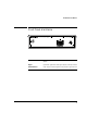
Front Panel at a Glance Front Panel at a Glance Access (green LED) Lights each time the interface pod is accessed by the network. Signal (yellow LED) Lights when a valid signal is present at the input connector. I/O Concentrator (UTP) Accepts an electrical signal from and provides a signal to the SUT.
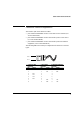
Cable and Line Connector Details Cable and Line Connector Details The HP E5129A 25.6 Mb/s Interface Pod’s connector pin configuration adheres to the specification defined in the IBM Corporation’s ATM 25.6 Mb/s PHY Compatibility Specification, Version 2.0, 15 October, 1993. Note In order to comply with EMC regulations, you must use one of the three connection cables that are supplied with the interface pod to connect to the system under test. See Connector Cable Configurations on the next page for details.
Cable and Line Connector Details Connector Cable Configurations The interface pod comes with three cables: • part number E1619-64300 connects a user device to the network (2 to 3 in the table below) • part number E1619-64301 connects the interface pod to a user device (1 to 2 in the table below) • part number E1619-64302 connects the interface pod to the network equipment (1 to 3 in the table below) The following table sets out the pin configurations for the three connector types: Pin 8 Pin 1 1.
To Set Up the Interface Pod To Set Up the Interface Pod Caution Handle the interface pod with care to avoid electrostatic discharge (ESD) damage during unpacking, installation, and operation. The connectors on the front and rear of the interface pod are susceptible to ESD. 1 Insert the interface pod into the analyzer. See “To Insert the Interface Pod” on page 7. The procedure is the same for all interface pods. 2 Connect the interface pod to the system under test.
To Set Up the Interface Pod To Insert the Interface Pod You can insert and remove interface pods at any time, even when the analyzer is powered on. Initially, you insert an interface pod when you set up the analyzer. Subsequently, you insert an interface pod when you change the physical layer interface that you want to monitor. 1 Hold the interface pod with the front panel connectors facing you and the Hewlett-Packard logo facing upwards. 2 Insert the interface pod into Port 1 or Port 2 of the analyzer.
To Set Up the Interface Pod To Remove the Interface Pod Gently press on the clip underneath the interface pod and pull the interface pod out of the analyzer. When you remove the interface pod, make sure you store it in a dust free location that meets the environmental requirements listed in “Environmental Specifications” on page 14. An electrostatic-safe bag has been supplied for the storage of each interface pod.
To Set Up the Interface Pod Receive (Rx) Some common system and test connections are • • • an intrusive system connection—network element remote loopback in-line test connections See the HP E5200A Broadband Service Analyzer User’s Guide or the Online Help for details about these system connections. The analyzer automatically sets the interface pod transmit and receive parameters and configures according to the signal it receives from the interface pod.
To Set Up the Interface Pod Automatic Configuration Parameters After you insert the interface pod and connect it to the SUT, the analyzer automatically configures to the 25.6 Mb/s electrical signal.
To Set Up the Interface Pod To Manually Configure the Interface Pod 1 From the Configure menu, select the appropriate port; then select Set Up. 2 Click the ATM25 tab. 3 Select the parameters you require. 4 Click to set the configuration or Click Auto to set the parameters to the default settings. A message warns you that the reconfiguration will cause some measurements and data to be lost and asks if you want to continue. Click OK.
What to Do Next X8 Timing Marker Source Setting When you change the X8 timing marker source setting, the traffic generator settings are cleared.
Standards and Specifications Standards and Specifications Communications Standards af-phy-004.400 ATM 25.6 Mb/s over Twisted Pair Cable, ATM Forum ITU-T I.432.5 B-ISDN User Interface for Physical Layer ATM 25.6 PHY compatibility specification IBM Corporation Physical Specifications Weight 1.0 kg ( 2.2 lbs) (nominal) Dimensions Height: Width: Length: 44 mm (1.73 inches) 149 mm (5.87 inches) 222 mm (8.
Standards and Specifications Environmental Specifications Parameter Min. Max. Notes Operating Temperature 5 oC (41 oF) 45 oC (113 oF) with two interface pods installed Storage Temperature –40 oC (–40 oF) 70 oC (158 oF) Humidity 15% 90% Altitude 14 Nominal 4.6 km (2.
Certification Hewlett-Packard Australia Ltd (HP) certifies that this product met its published specifications at the time of shipment from the factory. HP further certifies that its calibration measurements are traceable to the extent allowed by the calibration facilities of other International Standards Organization members. Warranty The hardware is warranted against defects in materials and workmanship.
Warnings The following general safety precautions must be observed during all phases of operation, service, and repair of this product. Failure to comply with these precautions or with specific warnings elsewhere in this manual violates safety standards of design, manufacture, and intended use of the product. Hewlett-Packard Australia Limited assumes no liability for the customer’s failure to comply with these requirements.
Avertissement Service et ajustement Cet appareil répond aux normes de la “Classe de sécurité 1” et est muni d’un fil de mise à la terre pour votre protection. Des “tensions dangereuses” résident dans cet appareil. Par conséquent, le service et l’ajustement doivent être effectué uniquement par une personne qualifiée. Pour prévenir les risques de choc électrique, la broche de mise à la terre du cordon d’alimentation ne doit pas être désactivée.
Right top margin for modules DECLARATION OF CONFORMITY According to ISO/IEC Guide 22 and EN 45014 body text drop Manufacturer’s Name Hewlett-Packard Australia Ltd Manufacturer’s Address Communications Measurements Division Australia 347 Burwood Highway Burwood East 3151 Victoria, Australia declares that the product: Product Name 25.6 Mb/s Interface Pod Model Numbers HP E5129A Product Options This declaration covers all options of the above product.