
Brocade 16Gb SAN Switch for HP BladeSystem c-Class User Guide

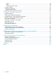
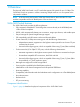
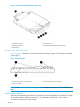
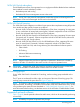
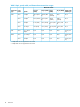
Table Of Contents
- Brocade 16Gb SAN Switch for HP BladeSystem c-Class
- Contents
- 1 Overview
- 2 Setup
- 3 Managing the 16Gb SAN Switch
- 4 Support and other resources
- A Regulatory information
- B Electrostatic discharge and grounding recommendations
- C SAN Switch technical specifications
- Glossary
- Index
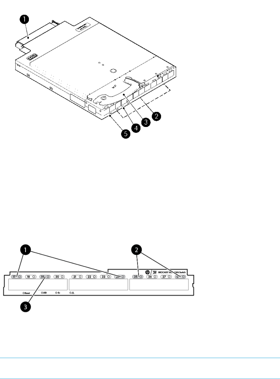
Figure 1 Brocade 16Gb SAN Switch components
2. External FC ports1. Midplane connector
4. Unit ID (UID), Health LED, and Status LEDs3. Installation handle
5. Reset button
Port side of the 16Gb SAN Switch
Figure 2 (page 6) identifies the 16Gb SAN Switch external ports (ports 17 through 20, and ports
21 through 0).
Figure 2 External ports
2. Trunk Group B (ports 25 through 0)1. Trunk Group A (ports 17 through 24)
3. User port number
NOTE: See Interpreting LED activity (page 22) for complete information on 16Gb SAN Switch
LEDs.
Internal ports summary
Sixteen logical internal ports (numbered 1 through 16) connect sequentially to server bays 1 through
16 with the enclosure midplane. Server bay 1 is connected to Switch Port 1, Server bay 2 is
connected to Switch port 2, and so forth.
6 Overview