
HP PCL/PJL reference (PCL 5 Color) - Technical Reference Manual


EN Using Color Modes 2-11
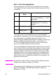
MODE 3: DIRECT BY PIXEL
This mode specifies a pixel as three, eight-bit components, thus the
name 24-bit direct color. Assuming the RGB color space with the
mandatory eight bits per component, the underlined bytes below
define the first pixel of row two.
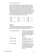
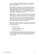
Example:
In the example below the data in the row transfer commands are
shown as two-digit hexadecimal numbers for clarity, even though the
actual data would be byte-aligned binary data. The example is for a
one-pixel-wide image.
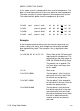
Byte 2 (Number of Bits per Index)
This command creates a palette regardless of the PEM chosen. This
byte determines the size of the created palette. The palette size is two
raised to the power of n (2
n
), where n is the bits per index.
• In the Indexed-by-Plane PEM, where the raster data is
interpreted as palette indices, this value determines the
number of planes required per row.
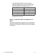
?*b#W row 1 r7–r0 g7–g0 b7–b0 . . .
?*b#W row 2 r7–r0 g7–g0 b7–b0 . . .
?*b#W row 3 r7–r0 g7–g0 b7–b0 . . .
?*v6W 00 03 00 08 08 08 Binary Data for CID command
represented in hexadecimal.
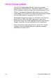
This command sets the color
space to RGB, the PEM to
Direct by Pixel. The palette size
is ignored. The last three bytes
must be 8.
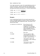
?*r1A Start raster
?*b3W 45 06 30 The three bytes specify a single
pixel. The first sets 45 as the red
component’s value, the second
sets the green value to 06, and
the third sets the blue value to
30.