
HP PCL/PJL reference (PCL 5 Printer Language) - Technical Reference Manual Part I


EN Raster Graphics Example 15-31
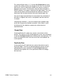
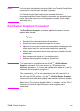
Raster Graphics Example
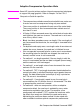
To transfer an unencoded raster graphic image (see Figure 15-11) in
the shape of an arrow, perform the following steps:
Table 15-10
1. Position the cursor:
E
C
*p300x400
Y
This moves the cursor to PCL Unit position
(300, 400) within the PCL coordinate
system.
2. Specify the raster graphics resolution:
E
C
*t75R This sets the raster graphics resolution to
75 dots-per-inch.
3. Specify the raster graphics presentation method:
E
C
*r0F This specifies that the raster graphics is
printed in the orientation of the logical
page.
4. Specify the left raster graphics margin:
E
C
*r1A This sets the left graphics margin to the
current X position (300).
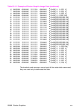
5. Transfer the raster data to the printer:
Divide the image into dot rows and transfer each dot row to the
printer as a string of bytes, as illustrated on the following page.
6. Signify the end of the raster graphic image transfer:
E
C
*rC This example prints the arrow as shown in
Figure 15-11.
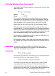
Table 15-11 Example of Raster Graphic Image Data
Raster Image Data Command Data
Dot
Row byte 1 byte 2 byte 3 byte 4 Decimal Equivalent
1
00000000 00000000 10000000 00000000
E
C
*b4W[ 0, 0,128, 0]
2
00000000 00000000 11000000 00000000
E
C
*b4W[ 0, 0,192, 0]
3
00000000 00000000 11100000 00000000
E
C
*b4W[ 0, 0,224, 0]
4
00000000 00000000 11110000 00000000
E
C
*b4W[ 0, 0,240, 0]
5
00000000 00000000 11111000 00000000
E
C
*b4W[ 0, 0,248, 0]