
HP PCL/PJL reference (PCL 5 Printer Language) - Technical Reference Manual Part II


21-12 The Polygon Group EN
To create a series of subpolygons, for example, the letter D, move the
pen to the starting location of the first subpolygon, then enter polygon
mode. Define the outer shape of the letter D using the appropriate
commands and coordinates, then close the subpolygon, staying in
polygon mode. Define the inner shape of the D, then exit polygon
mode. Now draw the subpolygons using either the Edge Polygon
(EP) or Fill Polygon (FP) command. For more information on entering
and exiting polygon mode, refer to the Polygon Mode (PM) command
discussed in this chapter.
In polygon mode, you can define points with the pen up or down.
However, the Edge Polygon (EP) command only draws between
points defined when the pen was down. In contrast, the Fill Polygon
(FP) command fills between all points, regardless of whether they
were defined when the pen was up or down. (Exception: the line
connecting two subpolygons is never drawn, and is not a fill
boundary.)
Filling Polygons
There are two methods which can be selected for filling polygons: the
even/odd fill method and the non-zero winding fill method.
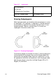
Even/Odd Fill Method
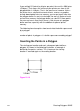
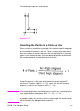
There is a simple way to determine which portions of a single polygon
or series of subpolygons is filled when you send a Fill Polygon (FP)
command using the default method 0, (fill using even/odd rule):
Draw a straight line extending from any point within an enclosed area
of the polygon to a point outside the polygon. FP fills the enclosed
area in question only if the line you have drawn intersects the edges
of the polygon an odd number of times. Figure 21-8 illustrates this
‘odd-even’ rule.