
HP PCL/PJL reference (PCL 5 Printer Language) - Technical Reference Manual Part II


21-48 The Polygon Group EN
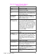
Table 21-26 Example: Filling then Edging vs.
Edging then Filling Chart
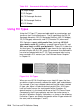
?E Reset the printer.
?%0B Enter HP-GL/2 mode.
IN; Initialize HP-GL/2 mode.
SP1; Select pen number 1. Even though there is
no physical pen, the SP command must be
used to enable printing.
SC-3000,3000,
-2000,2000,1;
Set up user scaling, with P1 being
(-3000,-2000) and P2 being (3000,2000).
Specify isotropic scaling.
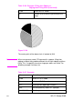
PA0,0;FT3,75,45;
WG-1000,90,180;
Enter absolute plotting mode and move to
user-unit position (0,0). Select fill type 3
(parallel lines), with 75 user-units between
lines and the lines slanted 45°. Fill a wedge
with the current fill pattern; use a radius of
1000 user-units, a starting angle of 90° and
a sweep angle of 180°. The zero-degree
reference point is on the left side of the
circle (indicated by the negative radius
parameter [-1000]).
EW-1000,90,180; Draw an outline (edge) around the same
wedge.
FT4,60,45;
WG-1000,330,120;
Select fill type 4 (cross-hatching), specifying
60 user-units between lines and with the
lines tilted at 45°. Fill a wedge that has the
same radius and center point, but with a
starting angle of 330° and a sweep angle
of 120°.
EW-1000,330,120; Edge the same wedge.
PR-60,110;FT1; Specify relative plotting and move the pen
60 user-units to the left and 110 units up.
Select fill type 1 (solid black).
WG-1000,270,60; Fill a wedge with a radius of 1000
user-units, a start angle of 270°, and a
sweep angle of 60°.
EW-1000,270,60; Edge the outline of the wedge that was
just filled.