
HP PCL/PJL reference (PCL 5 Printer Language) - Technical Reference Manual Part II


EN AC, Anchor Corner 22-7
SP1; Select pen number 1. The SP command must
be used to enable printing.
PA3000,3000; Specify absolute plotting and move to location
(3000,3000).
FT3,400,45;
RR1000,1000;
ER1000,1000;
Specify fill type number 3 (parallel lines), with
each line 400 plu apart and set at a 45° angle;
fill a rectangle using the current pen location
as the lower left corner, and a point 1000 plu
to the right and 1000 plu up as the upper
right corner; edge the outline of the rectangle
just filled.
PR1000,0;
FT4,400,45;
RR1000,1000;
ER1000,1000;
Move 1000 plu to the right; select fill type
number 4 (cross-hatch); create a rectangle
the same size as the first one, fill it with
cross-hatch, and edge its outline.
PR1000,0;
FT3,400,45;
RR1000,1000;
ER1000,1000;
Move to the right another 1000 plu and create
another rectangle of the same size, this time
filled with pattern number 3 again.
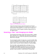
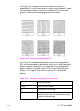
PA3000,1500;
AC3000,1500;
RR1000,1000;
ER1000,1000;
Move to absolute location (3000,1500); move
the anchor corner to location (3000,1500); fill
a rectangle with the same dimensions as the
previous three rectangles and edge its outline.
PA4000,1500;
AC4000,1500;
FT4,400,45;
RR1000,1000;
ER1000,1000;
Move to location (4000,1500) and specify the
location as the anchor corner; select fill type
number 4 (cross-hatch); fill and edge another
rectangle.
PA5000,1500;
AC5000,1500;
FT3,400,45;
RR1000,1000;
ER1000,1000;
Move to absolute location (5000,1500) and
specify that location as the anchor corner;
select fill type number 3; fill and edge another
rectangle.
?%0A Enter the PCL mode.
?E Send a reset to end the job and eject the page.
Table 22-3 Example: Changing the Anchor Corner (continued)