
HP PCL/PJL reference (PCL 5 Printer Language) - Technical Reference Manual Part II


18-10 The Picture Frame EN
Set Picture Frame Anchor Point
This command sets the location of the PCL Picture Frame anchor
point to the PCL cursor position.
E
C
* c 0 T
Default = 0
Range = 0
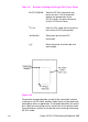
The position of the picture frame anchor point defines the location of
the upper left corner of the PCL Picture Frame. The “upper left” refers
to the corner for which X and Y coordinates are minimized when the
print direction is 0.
A parameter value of zero (
E
C
*c0T) specifies that the picture frame
anchor point should be set to the cursor position. Sending a cursor
move command prior to sending this command places the picture
frame anchor in the desired location. All parameter values other than
zero are ignored, but if you do not send a Set Picture Frame Anchor
command, the printer defaults the anchor point to the left edge of the
logical page and the default top margin.
Note The print direction command does not affect the physical location of
the anchor point or the picture frame.
Using this command defaults the location of P1 and P2, resets the
soft-clip window to the PCL Picture Frame boundaries, clears the
polygon buffer, and updates the HP-GL/2 pen position to the lower
left corner of the picture frame (if entered with
E
C
%0B), as viewed
from the current orientation.
Example:
To set the picture frame anchor point to a position 6 inches from the
left logical page boundary and 5 inches below the top margin, send:
E
C
*p1800x1500Y
E
C
*c0T
In this example, the cursor is first moved to the desired location (6
inches x 300 dots/inch = 1800 dots; 5 inches x 300 dots/inch = 1500
dots). Then the
E
C
*c0T command sets the picture frame anchor point
to that location.