
HP PCL/PJL reference (PCL 5 Printer Language) - Technical Reference Manual Part II


EN Default Settings 18-17
E
C
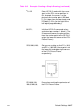
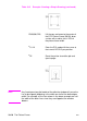
%1B Enter HP-GL/2 mode with the cursor
(pen) at the PCL cursor position. In
this example, the cursor is at the
picture frame anchor point (450 dots
[1.5 in.] down from the top margin and
675 dots [2.25 in.] to the right of the
left logical page boundary).
IN;SP1; Initialize HP-GL/2 command values
and select pen number 1 (black). (The
IN command moves the pen position
from the anchor point to the HP-GL/2
origin, the lower-left corner of the PCL
Picture Frame.)
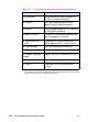
SC0,100,0,100; Set up user scaling so that P1 is (0,0)
and P2 is (100,100) (these points are
the lower-left and upper-right corners
of the PCL Picture Frame,
respectively).
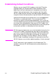
PD100,0,100,
100,0,100,0,0;
Draw a box marking the perimeter of
the PCL Picture Frame.
Table 18-2 Example: Creating a Simple Drawing (continued)