
HP PCL/PJL reference (PCL 5 Printer Language) - Technical Reference Manual Part II


19-6 The Configuration and Status Group EN
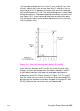
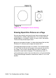
Figure 19-2 Same User-Unit Scaling with New P1 and P2
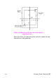
To further illustrate the flexibility of user-unit scaling, Figure 19-3
shows the P1 and P2 locations with negative user-unit values.
Note that the framework set by the scaling points P1 and P2 is not
a graphics limit. The user-unit coordinate system extends across the
entire PCL Picture Frame area. You can print to a point beyond P1 or
P2 as long as you are within the PCL Picture Frame. In Figure 19-3,
P1 is in the -X and -Y quadrant.
Note You can use coordinate points that are outside of the PCL Picture
Frame boundaries or even off of the page, but only that portion of the
vector graphics image that falls within the effective window is printed.
For example, you can draw a small portion of the circumference of a
circle with a 5-foot radius by moving the pen 5 feet from the page and
issuing a CI command (specifying a 5-foot radius); only the portion of
the arc that falls within the effective window is printed.