
HP PCL/PJL reference (PCL 5 Printer Language) - Technical Reference Manual Part II


19-16 The Configuration and Status Group EN
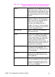
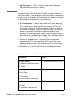
IN;SP1; Initialize HP-GL/2 command values and
select pen number 1 (black). (The IN
command moves the pen position from
the anchor point to the HP-GL/2 origin,
the lower-left corner of the PCL Picture
Frame.)
SC0,3.3867,0,-3.3867,2 Set-up a user scale with a user-unit
equal to 1/300 inch. Scale command
type 2, the scale is the ratio of plotter
units/user-units (1016 plotter
units-per-inch/300 dots-per-inch =
3.3867). The minus 2 Y-value changes
the HP-GL/2 Y direction to match that of
the PCL coordinate system.
IR0,100,0,100 Place P1 (point 0,0) at the top of the
PCL picture frame.
PU0,0; Lift the pen and move to (0,0) (upper left
corner — since HP-GL/2 coordinate
system now matches PCL coordinate
system). Every subsequent pen move
can be specified using the same
coordinate numbers in either mode. The
following commands demonstrate that
the grids are synchronized.
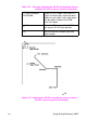
PU300,300;PD600,600; Lift the pen and move it to (300,300);
then draw a line to (600,600). This
draws a line at a 45° angle down from
the starting point.
E
C
%1A Enter the PCL mode with HP-GL/2’s
pen position being inherited as PCL’s.
CAP=(600,600).
E
C
*c300a4b0P Draw a horizontal line (rule) that is 300
PCL units wide by 4 PCL units. (Note
that the cursor position after a rule is
printed is at the beginning of the rule —
in this case, (600,600).)
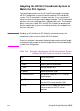
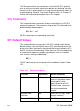
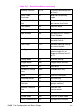
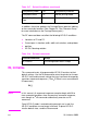
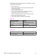
Table 19-5 Example: Adapting the HP-GL/2 Coordinate System
to Match the PCL System in Portrait Orientation