
HP PCL/PJL reference (PCL 5 Printer Language) - Technical Reference Manual Part II


19-42 The Configuration and Status Group EN
z
X
MIN
, X
MAX
, Y
MIN
, Y
MAX
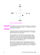
— These parameters represent the
user-unit X- and Y-axis ranges, respectively. For example,
SC0,15,0,10 indicates 15 user-units along the X-axis and
10 user-units along the Y-axis. As a result, the first and third
parameters (X
MIN
and Y
MIN
) are the coordinate pair that is
mapped onto P1; the second and fourth parameters (X
MAX
and Y
MAX
) are the coordinate pair mapped onto P2. Using the
same example, the coordinate location of P1 is (0,0) and P2
is (15,10). This is different from the IP command, where the
parameters are expressed as X,Y coordinate pairs rather than
as ranges.
Note X
MIN
cannot be set equal to X
MAX
, and Y
MIN
cannot be set equal
to Y
MAX
.
As their names suggest, you will normally want to specify X
MIN
smaller than X
MAX
, and Y
MIN
smaller than Y
MAX
. If you specify X
MIN
larger than X
MAX
and Y
MIN
larger than Y
MAX
, your illustration is drawn
as a mirror-image, reversed and/or upside down, depending on the
relative positions of P1 and P2.
The parameters of the SC command are always mapped onto the
current P1 and P2 locations. P1 and P2 retain these new values until
scaling is turned off or another SC command redefines the user-unit
values. Thus, the size of a user unit could change if any change is
made in the relative position and distance between P1 and P2 after
an SC command is executed.
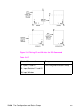
z Type — Specifies anisotropic or isotropic scaling.
Table 19-20
0 Anisotropic scaling. Allows a user-unit along the
X-axis to be a different size than user-units along the
Y-axis. Printed shapes are distorted when you use
anisotropic scaling. For example, a circle might be
drawn as an ellipse—oval-shaped instead of round.
(Left and bottom parameters are ignored for
anisotropic scaling.
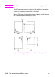
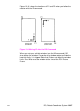
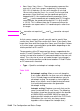
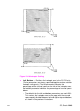
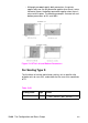
1 Isotropic scaling. Produces user-units that are the
same size on both the X- and Y-axes. The following
illustrations show how the printer adjusts the location
of (XMIN,YMIN) and (XMAX,YMAX) to create the
largest possible isotropic area within the P1/P2 limits.
(Remember, the user-units are always square
regardless of the shape of the isotropic area.)