HP SpectreXT Maintenance and Service Guide IMPORTANT! This document is intended for HP authorized service providers only.
© Copyright 2012 Hewlett-Packard Development Company, L.P. Intel is a trademark of Intel Corporation in the U.S. and other countries. Microsoft and Windows are U.S. registered trademarks of Microsoft Corporation. SD Logo is a trademark of its proprietor. The information contained herein is subject to change without notice. The only warranties for HP products and services are set forth in the express warranty statements accompanying such products and services.
Safety warning notice WARNING! To reduce the possibility of heat-related injuries or of overheating the device, do not place the device directly on your lap or obstruct the device air vents. Use the device only on a hard, flat surface. Do not allow another hard surface, such as an adjoining optional printer, or a soft surface, such as pillows or rugs or clothing, to block airflow. Also, do not allow the AC adapter to contact the skin or a soft surface, such as pillows or rugs or clothing, during operation.
iv Safety warning notice
Table of contents 1 Product description ........................................................................................................................................ 1 2 External component identification ................................................................................................................ 3 Display ..................................................................................................................................................
Solid-state drive ................................................................................................................. 33 WLAN module .................................................................................................................... 34 Fan ..................................................................................................................................... 35 RJ-45 module cover .....................................................................................
Restoring using the restore media ..................................................................................... 71 Changing the computer boot order .................................................................................... 71 Backing up and recovering your information ...................................................................................... 71 Using Windows Backup and Restore ................................................................................
viii
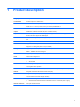
1 Product description Category Description Product Name HP ENVY Spectre XT Ultrabook PC Processors Intel® Core™' i7-3667U (2.0GHz, turbo up to 3.1GHz) 1600MHz/4M L3 Intel® Core™ ' i7-3517U (1.9GHz, turbo up to 3.0GHz) 1600MHz/4M L3 Intel® Core i5-3317U (1.7GHz, turbo up to 2.6GHz) 1600MHz/3M L3 Chipset Intel® HM76 - Platform Controller Hub (PCH - Panther Point-M) Graphics Intel® HD Graphics 4000 discrete-class graphics.
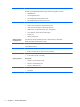
Category Description HP Multi-Format Digital Media Reader supports the following digital card formats: Ports Backlit keyboard/ pointing devices ● MultiMediaCard ● Secure Digital (SD) Card ● Secure Digital High-Capacity (SDHC) Card ● Secure Digital Extended Capacity (SDxC) Card ● 3-pin AC power (non-smart pin) ● Audio-in (mono microphone), supports jack detection ● Audio-out (stereo headphone), supports jack detection ● HDMI version 1.
2 External component identification Display Component Description (1) Turns off the display and initiates Sleep if the display is closed while the power is on. Internal display switch NOTE: The internal display switch is not visible from the outside of the computer. (2) WLAN antennas (2)* Send and receive wireless signals to communicate with wireless local area networks (WLANs). (3) Internal microphones (2) Record sound. (4) Webcam light On: The webcam is in use.
Button, speakers, and other components Component (1) Description Power button ● When the computer is off, press the button to turn on the computer. ● When the computer is on, press the button briefly to initiate Sleep. ● When the computer is in the Sleep state, press the button briefly to exit Sleep. ● When the computer is in Hibernation, press the button down briefly to exit Hibernation. CAUTION: Pressing and holding down the power button will result in the loss of unsaved information.
Component (3) Description Speakers (2) Produce sound. *The antennas are not visible from the outside of the computer. For optimal transmission, keep the areas immediately around the antennas free from obstructions. For wireless regulatory notices, see the section of the Regulatory, Safety, and Environmental Notices that applies to your country or region. These notices are located in Help and Support.
Keys Component Description (1) esc key Displays system information when pressed in combination with the fn key. (2) fn key Executes frequently used system functions when pressed in combination with the b key, the spacebar, or the esc key. (3) Windows logo key Displays the Windows Start menu. (4) Action keys Execute frequently used system functions. NOTE: On select models, the f5 action key turns the radiance backlight keyboard feature off or on.
Lights Component (1) Description Power light ● White: The computer is on. ● Blinking white: The computer is in the Sleep state, which is an energy-saving mode. The computer shuts off power to the display and other unneeded components. ● Off: The computer is off or in Hibernation. Hibernation is an energy-saving mode that uses the least amount of power. NOTE: For select models, the Intel® Rapid Start Technology feature is enabled at the factory.
Component Description (5) Caps lock light On: Caps lock is on, which switches the keys to all capital letters. (6) TouchPad light ● On: The TouchPad is off. ● Off: The TouchPad is on. TouchPad Component 8 Description (1) TouchPad on/off button Turns the TouchPad on or off. (2) TouchPad light ● On: The TouchPad is off. ● Off: The TouchPad is on. (3) TouchPad zone Moves the on-screen pointer and selects or activates items on the screen.
Left side Component (1) Description RJ-45 (network) lights (2) ● Green: The network is connected. ● Amber: Activity is occurring on the network. (2) RJ-45 (network) jack Connects a network cable. (3) HDMI port Connects an optional video or audio device, such as a high-definition television, or any compatible digital or audio device. (4) USB 3.0 port Connects an optional USB 3.0 device and provides enhanced USB power performance.
Right side Component (1) Description Power light ● White: The computer is on. ● Blinking white: The computer is in the Sleep state, which is an energy-saving mode. The computer shuts off power to the display and other unneeded components. ● Off: The computer is off or in Hibernation. Hibernation is an energy-saving mode that uses the least amount of power. NOTE: For select models, the Intel® Rapid Start Technology feature is enabled at the factory.
Component (6) (7) Description AC adapter light Power connector ● White: The AC adapter is connected and the battery is charged. ● Amber: The AC adapter is connected and the battery is charging. ● Off: The computer is using DC power. Connects an AC adapter.
Rear Component Description Vent Enables airflow to cool internal components. NOTE: The computer fan starts up automatically to cool internal components and prevent overheating. It is normal for the internal fan to cycle on and off during routine operation. Bottom Component (1) Description Speakers (4) Produce sound. NOTE: Two of the speakers are not shown in this illustration. (2) Vents (2) Enable airflow to cool internal components.
3 Illustrated parts catalog Service tag When ordering parts or requesting information, provide the computer serial number and model description provided on the service tag, which is located on the bottom of the computer. Item Description Function (1) Product name This is the product name affixed to the front of the computer. (2) Serial number (s/n) This is an alphanumeric identifier that is unique to each product.
Computer major components 14 Chapter 3 Illustrated parts catalog
Item Component Spare part number (1) Display panel 692891-001 (2) Top cover 689961-001 689962-001 (3) Antenna 692885-001 (4) Speaker kit (rear) 689952-001 (5) Backlit keyboard (with backlight) (includes keyboard cable): Backlit keyboard in black finish: For use in the United States 689943-001 For use in the United Kingdom and Singapore 689943-031 For use in Germany 689943-041 For use in France 689943-051 For use in Italy 689943-061 For use in Spain 689943-071 For use in Canada 6
Item Component Spare part number (13) RJ-45 cover 689948-001 (14) System board System board for use only with computer models equipped with an Intel 1.7GHz processor (includes processor and replacement thermal material). 689957-001 System board for use only with computer models equipped with an Intel 1.9GHz processor (includes processor and replacement thermal material). 689958-001 System board for use only with computer models equipped with an Intel 2.
Display assembly subcomponents Item Component Spare part number (1) Display bezel 692888–001 (2) 13.
Mass storage device Item Component Spare part number Hard drive (mSATA solid-state drive) 128-GB solid-state (SSD) drive 689953-001 256-GB solid-state (SSD) drive 689955-001 Screws (not illustrated) Miscellaneous parts Component Spare part number AC adapter (non-smart): 65-W PFC RC V 2-wire AC adapter (non-smart) for use in all countries and regions 613149-001 Power cord (3-pin, black, 1.
Component Spare part number For use in the People's Republic of China 490371-AA1 For use in Taiwan 490371-AB1 For use in South Korea 490371-AD1 For use in India 490371–D61 Screw Kit 689949-001 Sequential part number listing Spare part number Description 490371-001 Power cord for use in North America (3-pin, black, 1.83-m) 490371-011 Power cord for use in Australia (3-pin, black, 1.83-m) 490371-021 Power cord for use in Europe (3-pin, black, 1.
20 Spare part number Description 689943–031 Backlit keyboard in black finish for use in the United Kingdom and Singapore (includes keyboard cable) 689943–041 Backlit keyboard in black finish for use in Germany (includes keyboard cable) 689943–051 Backlit keyboard in black finish for use in France (includes keyboard cable) 689943–061 Backlit keyboard in black finish for use in Italy (includes keyboard cable) 689943–071 Backlit keyboard in black finish for use in Spain (includes keyboard cable) 6
Spare part number Description 689959-001 System board for use only with computer models equipped with an Intel 2.
4 Removal and replacement procedures CAUTION: This computer does not have user-replaceable parts. Only HP authorized service providers should perform the removal and replacement procedures described here. Accessing the internal part could damage the computer or void the warranty.
Drive handling CAUTION: Drives are fragile components that must be handled with care. To prevent damage to the computer, damage to a drive, or loss of information, observe these precautions: Before removing or inserting a hard drive, shut down the computer. If you are unsure whether the computer is off or in Hibernation, turn the computer on, and then shut it down through the operating system. Before handling a drive, be sure that you are discharged of static electricity.
Typical electrostatic voltage levels Relative humidity Event 24 10% 40% 55% Walking across carpet 35,000 V 15,000 V 7,500 V Walking across vinyl floor 12,000 V 5,000 V 3,000 V Motions of bench worker 6,000 V 800 V 400 V Removing DIPS from plastic tube 2,000 V 700 V 400 V Removing DIPS from vinyl tray 11,500 V 4,000 V 2,000 V Removing DIPS from Styrofoam 14,500 V 5,000 V 3,500 V Removing bubble pack from PCB 26,500 V 20,000 V 7,000 V Packing PCBs in foam-lined box 21,000 V
Packaging and transporting guidelines Follow these grounding guidelines when packaging and transporting equipment: ● To avoid hand contact, transport products in static-safe tubes, bags, or boxes. ● Protect ESD-sensitive parts and assemblies with conductive or approved containers or packaging. ● Keep ESD-sensitive parts in their containers until the parts arrive at static-free workstations. ● Place items on a grounded surface before removing items from their containers.
Equipment guidelines Grounding equipment must include either a wrist strap or a foot strap at a grounded workstation. ● When seated, wear a wrist strap connected to a grounded system. Wrist straps are flexible straps with a minimum of one megohm ±10% resistance in the ground cords. To provide proper ground, wear a strap snugly against the skin at all times. On grounded mats with banana-plug connectors, use alligator clips to connect a wrist strap.
Service label When ordering parts or requesting information, provide the computer serial number and model number provided on the service label, which is found on the bottom of the computer. Item Component Description (1) Product name This is the product name affixed to the front of the computer. (2) Serial number (s/n) This is an alphanumeric identifier that is unique to each product.
2. Remove the 6 remaining Phillips PM 5.5 millimeter screws (2) from the back and the middle of the base enclosure. 3. Separate the bottom enclosure from the unit at the rear edge and remove the bottom enclosure. NOTE: To remove the bottom enclosure, use a thin, non-conductive tool such as the HP Tool Shroud separator. This tool is available on the HP website.
Battery Description Spare part number 4-cell, 45WHr 3.05AH Li-ion battery 685989-001 Before removing the battery, follow these steps: 1. Shut down the computer. If you are unsure whether the computer is off or in Hibernation, turn the computer on, and then shut it down through the operating system. 2. Disconnect all external devices connected to the computer. 3.
4. Remove the battery from the computer (2). Reverse this procedure to install the battery.
RTC battery Description Spare part number RTC battery 686922-001 Before removing the RTC battery, follow these steps: 1. Shut down the computer. If you are unsure whether the computer is off or in Hibernation, turn the computer on, and then shut it down through the operating system. 2. Disconnect all external devices connected to the computer. 3. Disconnect the power from the computer by first unplugging the power cord from the AC outlet and then unplugging the AC adapter from the computer. 4.
Reverse this procedure to install the RTC battery on computer models. When installing the RTC battery, make sure the “+” sign faces up.
Solid-state drive Description Spare part number 128-GB mSATA solid-state drive (SSD) 689953-001 256-GB mSATA solid-state drive (SSD) 689955-001 Before removing the SSD, follow these steps: 1. Shut down the computer. If you are unsure whether the computer is off or in Hibernation, turn the computer on, and then shut it down through the operating system. 2. Disconnect all external devices connected to the computer. 3.
WLAN module Description Spare part number Intel Centrino® Advanced-N 6235 + Bluetooth combo w/* 2 Antennas (802.11 a/g/n) 670292-005 CAUTION: To prevent an unresponsive system, replace the wireless module only with a wireless module authorized for use in the computer by the governmental agency that regulates wireless devices in your country or region. If you replace the module and then receive a warning message, remove the module to restore device functionality, and then contact technical support.
Fan Description Spare part number Fan 692890-001 Before removing the fan: 1. Shut down the computer. If you are unsure whether the computer is off or in Hibernation, turn the computer on, and then shut it down through the operating system. 2. Disconnect all external devices connected to the computer. 3. Disconnect the power from the computer by first unplugging the power cord from the AC outlet and then unplugging the AC adapter from the computer. 4.
Before removing the RJ-45 module cover: 1. Shut down the computer. If you are unsure whether the computer is off or in Hibernation, turn the computer on, and then shut it down through the operating system. 2. Disconnect all external devices connected to the computer. 3. Disconnect the power from the computer by first unplugging the power cord from the AC outlet and then unplugging the AC adapter from the computer. 4. Remove the base enclosure (see Base enclosure on page 27). 5.
System board NOTE: The system board spare part kit includes replacement thermal material. Description Spare part number For use only with computer models equipped with an Intel 1.7GHz processor, but not WWAN capability (includes replacement thermal material) 689957-001 For use only with computer models equipped with an Intel 1.9GHz processor, but not WWAN capability (includes replacement thermal material) 689958-001 For use only with computer models equipped with an Intel 2.
2. 38 ● Backlit keyboard cable (4) ● Backlit keyboard light cable (5) ● TouchPad LED cable (6) ● RTC cable (7) ● TouchPad cable (8) ● Power connector cable (9) Remove the 5 Phillips PM 2.0x3.0 screws (1).
3. Remove the system board (2). Reverse this procedure to install the system board.
Heat sink Description Spare part number Heat sink 689938-001 NOTE: To properly ventilate the computer, allow at least 7.6 cm (3 in) of clearance on the left side of the computer. The computer uses an electric fan for ventilation. The fan is controlled by a temperature sensor and is designed to turn on automatically when high temperature conditions exist.
2. Remove the heat sink (2). Reverse this procedure to install the heat sink.. CAUTION: These screws must be installed in the sequence that is marked on the heat sink so that the correct pressure is applied to the processor and other components. Speakers Description Spare part number Speaker Kit, front (includes front speaker and cable) 689951-001 Speaker Kit, rear (includes front speaker and cable) 689952-001 Before removing the front speakers, follow these steps: 1. Shut down the computer.
3. Remove the Phillips PM screws securing each half of the front speaker (2). 4. Remove the speaker cables (3) that are routed on each side of the front area. 5. Remove the speakers (4). Reverse this procedure to install the front speakers. Before removing the rear speaker, follow these steps; 1. Shut down the computer. If you are unsure whether the computer is off or in Hibernation, turn the computer on, and then shut it down through the operating system. 2.
2. Remove the 2 Phillips PM 4.0 millimeter screws (2), and then remove the rear speakers (3). USB/Audio board Description Spare part number USB/Audio board (includes digital media card reader) 689947-001 Before removing the USB/Audio board, follow these steps: 1. Shut down the computer. If you are unsure whether the computer is off or in Hibernation, turn the computer on, and then shut it down through the operating system. 2. Disconnect all external devices connected to the computer. 3.
6. Remove the USB/Audio board (6). Reverse this procedure to install the USB/Audio board.
TouchPad module Description Spare part number TouchPad button board (includes cable) 689946-001 Before removing the TouchPad button board, follow these steps: 1. Shut down the computer. If you are unsure whether the computer is off or in Hibernation, turn the computer on, and then shut it down through the operating system. 2. Disconnect all external devices connected to the computer. 3.
5. Remove the TouchPad button board and cable (2). Reverse this procedure to install the TouchPad button board and cable. TouchPad LED board Description Spare part number TouchPad LED board 689945-001 Remove the TouchPad LED board: 1. 46 Disconnect the TouchPad LED board cable (1).
2. Unclip the TouchPad LED board (2), and then remove it (3). Power connector cable Description Spare part number Power connector cable (includes bracket) 689937-001 Before removing the power connector cable, follow these steps: 1. Shut down the computer. If you are unsure whether the computer is off or in Hibernation, turn the computer on, and then shut it down through the operating system. 2. Disconnect all external devices connected to the computer. 3.
2. Remove the 2 screws that secure the right hinge (1), and then rotate the hinge to the open position (2). 3. Disconnect the power connector cable (1), and then remove the power connector and cable (2). Reverse this procedure to install the power connector and cable.
Power button board Description Spare part number Power button board 689944-001 Before removing the Power button board, follow these steps: 1. Shut down the computer. If you are unsure whether the computer is off or in Hibernation, turn the computer on, and then shut it down through the operating system. 2. Disconnect all external devices connected to the computer. 3.
4. Remove the Power button board (3). NOTE: The Power button board's cable is soldered on. .
Display panel Description Spare part number 13.3-in, LED, BrightView SVA display panel 692891-001 Before removing the display panel, follow these steps: 1. Shut down the computer. If you are unsure whether the computer is off or in Hibernation, turn the computer on, and then shut it down through the operating system. 2. Disconnect all external devices connected to the computer. 3.
52 7. Remove the top cover from the display assembly. 8. Loosen the bottom edge of the plastic bezel cover (1) from all four sides of the display panel. 9. Loosen the left and right side edges of the plastic bezel cover (2), and then loosen the top edge of the plastic bezel cover (3). Remove the plastic bezel cover (4).
10. Slide the hinge covers outwards (1), and then release the secondary hinge covers (2). NOTE: Remove any tabs or tape adhering to the display panel. 11. Remove the 6 Phillips PM screws (1) from the hinge brackets, and then remove the hinge brackets (2).
12. Rotate the hinges to the open position (1), and then remove the 2 Phillips PM screws (2). Remove the display panel (3). 13. Remove the adhesive tape from the display panel cable connector (1). 14. Disconnect the display panel cable connector (2) from the display panel (2). 15. Remove the panel cable from the clips on the left edge (1), and then loosen the cable from the adhesive tape (2).
16. Disconnect the cable from the webcam (3). Reverse this procedure to install the display panel. Webcam assembly Description Spare part numbers Webcam assembly 689965-001 Before removing the webcam assembly: 1. Shut down the computer. If you are unsure whether the computer is off or in Hibernation, turn the computer on, and then shut it down through the operating system. 2. Disconnect all external devices connected to the computer. 3.
▲ Lift the webcam from the display panel (1), and then remove the webcam assembly (2). Backlit keyboard NOTE: The keyboard spare part kit includes a keyboard cable.
Before removing the keyboard, follow these steps: 1. Shut down the computer. If you are unsure whether the computer is off or in Hibernation, turn the computer on, and then shut it down through the operating system. 2. Disconnect all external devices connected to the computer. 3. Disconnect the power from the computer by first unplugging the power cord from the AC outlet and then unplugging the AC adapter from the computer. 4. Remove the display panel (see Display panel on page 51). 5.
4. Remove the keyboard bracket (1). Make sure the keyboard cables are disengaged from the bracket as you remove the keyboard bracket (2). Make sure to push the keyboard cables through the bracket. 5. Remove the 3 black Phillips PM 2x2 screws (1), and then remove the 3 Phillips PM 1.6 screws (2). 6. Remove the keyboard (3). Reverse this procedure to install the keyboard. WLAN antenna cables Description Spare part numbers WLAN antennas 670292-005 Before removing the antenna cables: 58 1.
3. Disconnect the power from the computer by first unplugging the power cord from the AC outlet and then unplugging the AC adapter from the computer. 4. Remove the display panel (see Display panel on page 51). 5. Remove the base enclosure (see Base enclosure on page 27). 6. Disconnect the battery cable (see Battery on page 29). Remove the WLAN antenna cables: ▲ Remove the WLAN antenna transceivers (1), and then remove the cables (2) from the right and left sides of the hinge.
Before removing the top cover from the display panel, follow these steps: 1. Shut down the computer. If you are unsure whether the computer is off or in Hibernation, turn the computer on, and then shut it down through the operating system. 2. Disconnect all external devices connected to the computer. 3. Disconnect the power from the computer by first unplugging the power cord from the AC outlet and then unplugging the AC adapter from the computer.
5 Setup Utility (BIOS) and System Diagnostics Using Setup Utility Setup Utility, or Basic Input/Output System (BIOS), controls communication between all the input and output devices on the system (such as disk drives, display, keyboard, mouse, and printer). Setup Utility includes settings for the types of peripherals installed, the startup sequence of the computer, and the amount of system and extended memory. NOTE: Use extreme care when making changes in Setup Utility.
Navigating and selecting in Setup Utility To navigate and select in Setup Utility, follow these steps: 1. 2. Turn on or restart the computer, and then press esc while the “Press the ESC key for Startup Menu” message is displayed at the bottom of the screen. ● To select a menu or a menu item, use the tab key and the keyboard arrow keys and then press enter, or use a pointing device to click the item.
Restoring factory settings in Setup Utility NOTE: Restoring defaults will not change the hard drive mode. To return all settings in Setup Utility to the values that were set at the factory, follow these steps: 1. Turn on or restart the computer, and then press esc while the “Press the ESC key for Startup Menu” message is displayed at the bottom of the screen. 2. Press f10 to enter Setup Utility. 3. Use the arrow keys to select Exit > Load Setup Defaults. 4. Follow the on-screen instructions. 5.
Determining the BIOS version To determine whether available BIOS updates contain later BIOS versions than those currently installed on the computer, you need to know the version of the system BIOS currently installed. BIOS version information (also known as ROM date and System BIOS) can be displayed by pressing fn+esc (if you are already in Windows) or by using Setup Utility. 1. Start Setup Utility (BIOS). 2. Use the arrow keys to select Main. 3.
4. Double-click the file that has an .exe extension (for example, filename.exe). The BIOS installation begins. 5. Complete the installation by following the on-screen instructions. NOTE: After a message on the screen reports a successful installation, you can delete the downloaded file from your hard drive. Using System Diagnostics System Diagnostics allows you to run diagnostic tests to determine if the computer hardware is functioning properly.
6 Specifications Computer specifications Metric U.S. Width 29.16 cm 11.48 in Depth 2.15 cm 8.46 in Height (front to back) 2.11 to 3.19 cm 0.83 to 1.26 in With 6-cell battery 1.60 kg 3.53 lb With 3-cell battery 1.46 kg 3.22 lb Dimensions Weight Input power Operating voltage and current 18.5 V dc @ 3.
Metric Contrast ratio 200:1 (typical) Brightness 200 nits (typical) U.S. Pixel resolution Pitch 0.197 mm × 0.197 mm Format 1366 × 768 Configuration RGB vertical stripe Backlight LED Character display 80 × 25 Total power consumption 2.0 W Viewing angle ±65° horizontal, ±50° vertical (typical) 13.
7 Backup and recovery Your computer includes tools provided by the operating system and HP to help you safeguard your information and restore it if ever needed.
● Only one set of recovery discs or one recovery flash drive can be created per computer. NOTE: If you are creating recovery discs, number each disc before inserting it into an optional external optical drive (purchased separately). ● If necessary, you can exit the program before you have finished creating the recovery discs or recovery flash drive. The next time you open HP Recovery Manager, you will be prompted to continue the backup creation process.
To restore the computer from the recovery partition, follow these steps: 1. Access HP Recovery Manager in either of the following ways: ● Select Start > All Programs > Security and Protection > HP Recovery Manager > HP Recovery Manager. – or – ● 70 Turn on or restart the computer, and then press esc while the “Press the ESC key for Startup Menu” message is displayed at the bottom of the screen. Then, press f11 while the “F11 (System Recovery)” message is displayed on the screen. 2.
Restoring using the restore media 1. If possible, back up all personal files. 2. Insert the first recovery disc into an optional external optical drive (purchased separately), and then restart the computer. – or – Insert the recovery flash drive into a USB port on your computer, and then restart the computer. NOTE: If the computer does not automatically restart in the HP Recovery Manager, the computer boot order needs to be changed. 3. Press f9 at system bootup. 4.
Guidelines: ● Create system restore points using the Windows® System Restore feature, and periodically copy them to an optical disc using an optional external optical drive (purchased separately) or an external hard drive. For more information on using system restore points, refer to Using Windows system restore points on page 73. ● Store personal files in the Documents library and back up this folder periodically.
Using Windows system restore points A system restore point allows you to save and name a snapshot of your hard drive at a specific point in time. You can then recover back to that point if you want to reverse subsequent changes. NOTE: Recovering to an earlier restore point does not affect data files saved or e-mails created since the last restore point. You also can create additional restore points to provide increased protection for your files and settings.
8 Power cord set requirements The wide-range input feature of the computer permits it to operate from any line voltage from 100 to 120 volts AC, or from 220 to 240 volts AC. The 3-conductor power cord set included with the computer meets the requirements for use in the country or region where the equipment is purchased. Power cord sets for use in other countries and regions must meet the requirements of the country or region where the computer is used.
Country/region Accredited agency Applicable note number Japan JIS 3 The Netherlands KEMA 1 New Zealand SANZ 1 Norway NEMKO 1 The People's Republic of China CCC 4 Saudi Arabia SASO 7 Singapore PSB 1 South Africa SABS 1 South Korea KTL 5 Sweden SEMKO 1 Switzerland SEV 1 Taiwan BSMI 6 Thailand TISI 1 The United Kingdom ASTA 1 The United States UL 2 1. The flexible cord must be Type HO5VV-F, 3-conductor, 0.75-mm² conductor size.
9 Recycling When a non-rechargeable or rechargeable battery has reached the end of its useful life, do not dispose of the battery in general household waste. Follow the local laws and regulations in your area for battery disposal. HP encourages customers to recycle used electronic hardware, HP original print cartridges, and rechargeable batteries. For more information about recycling programs, see the HP Web site at http://www.hp.com/recycle.
Index A AC adapter 11 AC adapter, spare part numbers 18, 19 action keys identifying 6 audio, product description 1 audio-out (headphone) jacks 10 B backing up customized window, toolbar, and menu bar settings 72 personal files 72 base enclosure removal 27 spare part numbers 27 base enclosure, spare part number 19 battery removal 29 spare part numbers 16, 19, 29 Blu-ray ROM DVD±R/RW Super Multi Double-Layer Drive precautions 23 buttons power 4 TouchPad on/off 8 C cables, service considerations 22 caps lock l
M mass storage device precautions 23 removal 33 spare part numbers memory module product description microphone product description model description 27 model name 1 mute light, identifying 18, 33 1 1 7 N network jack, identifying 9 O operating system, product description 2 optical drive precautions 23 P packaging guidelines 25 plastic parts, service considerations 22 pointing device, product description 2 ports HDMI 9 product description 2 USB 10 USB 3.
WLAN module removal 34 spare part numbers 19, 34 workstation guidelines 25 Index 79