HP StorageWorks Modular Smart Array 20 Maintenance and Service Guide July 2004 (First Edition) Part Number 365511-001
© Copyright 2004 Hewlett-Packard Development Company, L.P. The information contained herein is subject to change without notice. The only warranties for HP products and services are set forth in the express warranty statements accompanying such products and services. Nothing herein should be construed as constituting an additional warranty. HP shall not be liable for technical or editorial errors or omissions contained herein.
Contents About This Guide Audience Assumptions..................................................................................................................................v Technician Notes...........................................................................................................................................v Where to Go for Additional Help.................................................................................................................vi Telephone Numbers ...........
Contents Chapter 4 Specifications Power Specifications..................................................................................................................................4-1 Environmental Specifications ....................................................................................................................4-1 Physical Specifications ..............................................................................................................................
About This Guide This maintenance and service guide can be used for reference when servicing the HP StorageWorks Modular Smart Array 20 enclosure. WARNING: To reduce the risk of personal injury from electric shock and hazardous energy levels, only authorized service technicians should attempt to repair this equipment. Improper repairs can create conditions that are hazardous. Audience Assumptions This guide is for service technicians.
About This Guide CAUTION: To properly ventilate the system, you must provide at least 7.6 cm (3.0 in.) of clearance at the front and back of the enclosure. CAUTION: The enclosure is designed to be electrically grounded (earthed). To ensure proper operation, plug the AC power cord into a properly grounded AC outlet only. NOTE: Any indications of component replacement or printed wiring board modifications may void any warranty.
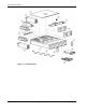
1 Illustrated Parts Catalog The spare parts for the enclosure are illustrated on the following page.
Illustrated Parts Catalog Figure 1-1: Enclosure parts 1-2 HP StorageWorks Modular Smart Array 20 Maintenance and Service Guide
Illustrated Parts Catalog Item Description Spare part number 1 Chassis Not spared 2 Power supply unit 349800-001 3 Fan assembly 349798-001 4 Button and LED panel Not spared 5 UID circuit board 361183-001 6 Controller module Module shell (sheet metal) with controller board, 349797-001 Upper battery pack with cable, 349799-001 Lower battery pack, 307132-001 Cache board with battery, 309521-001 7 Enclosure lid Not spared 8 VRM power supply 361741-001 9 Midplane 349795-001 10 Bac
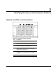
2 Identifying Enclosure and Component Features Buttons and LEDs on Enclosure Rear Figure 2-1: Enclosure buttons and LEDs Item Description 1 Arrow buttons (for future use) 2 Enclosure ID display— Indicates the ID number assigned to the enclosure during drive configuration 3 Unit identification button— Causes the blue LED on all drives in the enclosure to be illuminated 4 Enclosure monitor status LED— Illuminates green to indicate that the enclosure monitor (Global Service Indicator, or GSI) is fun
Identifying Enclosure and Component Features Disk Drives and Drive Blanks The drive bays on the front of the enclosure are numbered as follows: 1 4 7 10 2 5 8 11 3 6 9 12 The features of the drives and blanks are illustrated in Figure 2-2.
Identifying Enclosure and Component Features Table 2-1: Interpreting the Drive Status LEDs Online LED (green) Fault/ID LED (amber/blue) Meaning On, off, or flashing Alternating between amber and blue The drive has failed, or a predictive failure alert* has been received for this drive. It has also been selected by a management application. On, off, or flashing Steadily blue The drive is operating normally, and it has been selected by a management application.
Identifying Enclosure and Component Features Controller Module Figure 2-3: Controller module Item 2-4 Description 1 Upper cache battery 2 Finger hook 3 Bicolor status LED (green or amber) 4 VHDCI connector (for connecting to a sixth-generation Smart Array controller or an MSA1500 cs enclosure) 5 Service port 6 Release lever 7 Controller cache (lower cache battery just visible) HP StorageWorks Modular Smart Array 20 Maintenance and Service Guide
Identifying Enclosure and Component Features Fan Assembly Figure 2-4: Fan assembly Item Description 1 Bicolor status LED (green or amber) 2 Release lever HP StorageWorks Modular Smart Array 20 Maintenance and Service Guide 2-5
Identifying Enclosure and Component Features Power Supply Unit Figure 2-5: Power supply unit Item Description 1 Handle 2 AC power inlet 3 Release lever 4 Bicolor status LED (green or amber) WARNING: Do not use the handles on the power supply units to lift or hold the enclosure. These handles are designed only for holding the power supply units or removing them from the enclosure, not for supporting the weight of the enclosure.
3 Removing and Replacing Components Some enclosure components are hot-pluggable, while others should be replaced only after you have disconnected the enclosure from the AC power source.
Removing and Replacing Components • Use a wrist strap connected by a ground cord to a grounded workstation or computer chassis. Wrist straps are flexible straps with a minimum of 1 megohm ± 10 percent resistance in the ground cords. To provide proper ground, wear the strap snug against the skin. • Use heel straps, toe straps, or boot straps at standing workstations. Wear the straps on both feet when standing on conductive floors or dissipating floor mats. • Use conductive field service tools.
Removing and Replacing Components 2. Pull the drive out of the enclosure by about 3 cm (1 inch) so that it is disconnected from the backplane connector. CAUTION: A drive with a rapidly spinning disk can be difficult to hold securely. To decrease the chance of dropping the drive, do not remove it completely from the enclosure until the disk has stopped rotating. This usually takes a few seconds. 3. When the disk is no longer spinning, remove the drive from the enclosure.
Removing and Replacing Components Controller Module 1. Back up the data on the system. 2. Stop data transfers. 3. Disconnect the VHDCI cable. 4. Squeeze the release lever and the finger hook together while pulling the controller module out of the enclosure. 5. Transfer the cache and batteries from the degraded controller module to the replacement controller module. 6. Insert the replacement controller module into the enclosure until it is firmly seated in the enclosure. 7.
Removing and Replacing Components 3. Remove the upper battery unit (1). a. Loosen the thumbscrews (2). b. Disconnect the battery cable (3). c. Slide the upper battery unit toward the rear of the controller module and lift it out. 4. If the battery pack in the upper battery unit must be replaced, remove it as follows: a. Unwind the battery cable completely from around the battery pack. b. Push the two plastic retainer tabs up and through the slots in the battery case (1). c.
Removing and Replacing Components 5. Remove the cache from the controller board: a. Open the ejector levers on each side of the memory module socket (1). b. Pull the cache board out of the socket (2). If the cache battery must be replaced: a. Press down on the plastic retainer tabs and push them through to the other side of the cache board (3). b. Lift the battery pack off the cache board. 6. Replace whichever battery pack is degraded with the new battery pack. 7.
Removing and Replacing Components 2. Rotate the slot in the enclosure lid lever to the unlocked position (1), as indicated by the open padlock embossed in the lever. 3. Pull the lever toward the front of the enclosure (2). 4. Lift the lid off the enclosure (3). To replace the lid: 1. Position the lid on the chassis so that the peg on the chassis (1) fits into the hole under the lid lever, and the flanged pegs (2) on the inner edge of the lid fit into slots (3) on the side of the enclosure. 2.
Removing and Replacing Components 4. Disconnect the ribbon cable from the midplane board. 5. Loosen the captive thumbscrews (1). 6. Pull or push against the captive thumbscrews to slide the midplane board toward the rear of the enclosure (2). 7. Tilt the board lengthwise and manipulate it to get it out of the chassis. To replace the midplane board: 1.
Removing and Replacing Components Backplane Board 1. Remove the midplane board. 2. Remove the knurled thumbscrew on the backplane board (1). 3. Tilt the lower portion of the backplane board upward and lift the board out of the enclosure (2). To install a backplane board: 1. Position the board against the chassis so that the three rounded prongs on the chassis engage with the corresponding holes in the board. 2. Tighten the thumbscrew.
Removing and Replacing Components UID Circuit Board 1. Disconnect the ribbon cable from the UID circuit board. 2. Remove the two screws (1). 3. Remove the UID LED and button panel (2). NOTE: Take care that the plastic window does not fall out of the panel and get lost. 4. Tilt the edge of the board upward, and pull the board out of the chassis (3). To install a UID circuit board, reverse this procedure. VRM Power Supply 1. Pull out the latches on both sides of the socket (1). 2.
4 Specifications Power Specifications Table 4-1: AC Input Requirements Nominal Value Range Frequency (±5%) 50 or 60 Hz 47 to 63 Hz Voltage 110 or 240 V 90 to 254 V RMS (autoranging) Steady state maximum current At 240 V: 1.8 A (one power supply) or 1.9 A (two power supplies) — At 120 V: 3.7 A (one power supply) or 3.9 A (two power supplies) Standby current 0.21 A at 240 V, 60 Hz — 0.
Specifications Physical Specifications Table 4-3: Enclosure Specifications Form Unpacked Dimensions Weight International (cm) US (in) 59.7 x 48.8 x 8.8 23.5 x 19.2 x 3.5 14 kg (32 lb) empty 24 kg (53 lb) with components In shipping carton 83.8 x 81.3 x 27.4 33.0 x 32.0 x 10.8 25 kg (55 lb) empty 34 kg (75 lb) with components Table 4-4: Specifications of Components Form 4-2 Dimensions Weight International (cm) US (in) Fan assembly 26.8 x 6.0 x 6.0 10.6 x 2.4 x 2.4 0.50 kg (1.