Cisco Gigabit Ethernet Switch Module for HP BladeSystem p-Class Hardware Installation Guide February 2005 (First Edition) Part Number 380264-001
© Copyright 2005 Hewlett-Packard Development Company, L.P. The information contained herein is subject to change without notice. The only warranties for HP products and services are set forth in the express warranty statements accompanying such products and services. Nothing herein should be construed as constituting an additional warranty. HP shall not be liable for technical or editorial errors or omissions contained herein. Microsoft, Windows, and Windows NT are U.S.
Contents About This Guide Technician Notes........................................................................................................................................ vii Where to Go for Additional Help.............................................................................................................. viii Telephone Numbers ............................................................................................................................
Contents Remote Access from a Workstation via Ethernet to the Switch with No DHCP Service Available to the Switch ..........................................................................................................................................2-12 Connecting to the Console Port.........................................................................................................2-13 Running POST .....................................................................................................
Contents Appendix D Configuring the Switch Using CLI Overview .................................................................................................................................................. D-1 Accessing the CLI Through the Console Port .......................................................................................... D-1 Connecting to the Console Port................................................................................................................
About This Guide This guide can be used for reference when servicing the Cisco Gigabit Ethernet Switch Module (CGESM). WARNING: To reduce the risk of personal injury from electric shock and hazardous energy levels, only authorized service technicians should attempt to repair this equipment. Improper repairs can create conditions that are hazardous. Technician Notes WARNING: Only authorized technicians trained by HP should attempt to repair this equipment.
About This Guide Where to Go for Additional Help In addition to this guide, the following information sources are available at http://www.hp.
1 Product Overview Overview The Cisco Gigabit Ethernet Switch Module (CGESM)—also referred to as the switch—is an Ethernet switch to which you can connect devices such as servers, routers, and other switches. This chapter provides a functional overview of the switch.
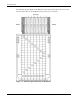
Product Overview The following diagram illustrates the Ethernet signal connectivity between server bays and the interconnect bays via the backplane for the p-Class server enclosure.
Product Overview The following diagram illustrates the Ethernet signal connectivity between server bays and the interconnect bays via the backplane for p-Class server enclosures with enhanced backplane components that support high-density blade servers.
Product Overview Front Panel Figure 1-3: Front Panel Table 1-1: Front Panel 1-4 Item Description 1 System (Syst) LED 2 Mode LEDs 3 Mode button 4 Downlink ports 1-16 LEDs 5 Cross-Connect (XC) ports 17 and 18 LEDs 6 Uplink ports 19-22 LEDs 7 Front panel (FP) Ethernet ports 23 and 24 LEDs 8 Ethernet port 23 9 Ethernet port 24 10 Console port 11 Pwr/Rst button Cisco Gigabit Ethernet Switch Module for HP BladeSystem p-Class Hardware Installation Guide
Product Overview System LED The System (Syst) LED shows whether the system is receiving power and is functioning properly. Table 1-2 lists the LED colors and their meanings. Table 1-2: System (Syst) LED Color System Status Off System is not powered on. Green System is operating normally. Amber System is receiving power but is not functioning properly. Port LEDs and Modes Each RJ-45 port and SFP module slot has a port LED.
Product Overview Table 1-4: Meaning of LED Colors in Different Modes on the Switch Port Mode LED Color Meaning STAT (port status) Off No link or port was administratively shut down. Green Link present. Blinking green Activity. Port is transmitting or receiving data. Alternating green-amber Link fault. Error frames can affect connectivity, and errors such as excessive collisions, CRC errors, and alignment and jabber errors are monitored for a link-fault indication.
Product Overview Ethernet Ports The switch 10/100/1000BASE-T ports configure themselves to operate at the speed of attached devices. If the attached ports do not support autonegotiation, you can explicitly set the speed and duplex parameters. Connecting devices that do not autonegotiate or that have their speed and duplex parameters manually set can reduce performance or result in no linkage.
Product Overview Rear Panel The following figure illustrates the SFP ports for the 10/100/1000BASE-T copper or 1000BASE-SX fiber uplinks (ports 19-22).
Product Overview MAC Address The label shown in Figure 1-5 shows where to find the Base MAC address of the switch. It is not actually used on any interface. Actual MAC addresses that will be used for interfaces such as physical interfaces (GigabitEthernet 0/1 to GigabitEthernet 0/24) or logical interfaces (Vlan1, etc.) can be derived from the Base MAC address.
Product Overview Management Options The switch offers several management options: • Device Manager Device Manager is a graphical user interface that can be launched from anywhere in your network through a web browser. Device Manager is already installed on the switch, and no additional installation is required. From Device Manager, you can configure and monitor a switch or launch a telnet session to the CLI.
2 Switch Installation Overview This chapter describes how to set up and install the switch and the SFP modules.
Switch Installation Verifying Package Contents NOTE: Carefully remove the contents from the shipping container, and check each item for damage. If any item is missing or damaged, contact your Cisco representative or reseller for support. Return all packing material to the shipping container, and save it.
Switch Installation Installing the Switch and SFP Modules This section describes how to: • Install a new switch • Install SFP modules Installation Guidelines Observe the following guidelines during installation: • For optimal performance, it is required that the switches be installed in the server blade enclosure in pairs. Each server blade enclosure requires two switches for proper connectivity. Both switches are identical.
Switch Installation Table 2-1: Fiber-Optic SFP Module Port Cabling Specifications SFP Module Wavelength (nanometers) Fiber Type Core Size (micron) Modal Bandwidth (MHz/km) Cable Distance 1000BASE-SX 850 MMF 62.5 160 722 feet (220 m) 62.5 200 902 feet (275 m) 50 400 1640 feet (500 m) 50 500 1804 feet (550 m) 10/100/1000BASE-T 328 feet (100 meters) Installing a Switch If the server blade enclosure has power applied, the switch automatically begins to power up when installed.
Switch Installation Insert the switch into the enclosure. Figure 2-1: Installing the Switch Installing SFP Modules CAUTION: We strongly recommend that you do not install or remove fiber-optic SFP modules with cables attached because of the potential damage to the cables, the cable connector, or the optical interfaces in the SFP module. Disconnect all cables before removing or installing an SFP module. Removing and installing an SFP module can shorten its useful life.
Switch Installation 3. Insert the SFP module and close the SFP latch. The orientation of an SFP module within a switch varies according to the SFP module port. Be sure that the SFP module is in the right position before inserting. Refer to the diagrams below.
Switch Installation Planning the Switch Configuration Before you configure the switch, HP recommends that you plan the configuration. As you plan, consider your default settings, security issues and privileges, and whether you want to configure each switch manually or configure multiple switches at the same time. Default Settings The switch ships with a default configuration in which all ports are enabled except Cross-Connect ports 17 and 18.
Switch Installation • Port parameters — Ports 17 and 18 are administratively down. — Operating mode is Layer 2 (switchport). — Interface speed and duplex mode is autonegotiate. — Auto-MDIX is enabled. — Flow control is off. — Power over Ethernet (PoE) is autonegotiate. • No Smartports macros are defined. • VLANs — Default VLAN is VLAN 1. — VLAN trunking setting is dynamic auto (DTP). — Trunk encapsulation is negotiate. — VTP mode is server. — VTP version is Version 1. — Voice VLAN is disabled.
Switch Installation • Syslog messages are enabled and are displayed on the console. • SNMP is disabled (Version 1). • No ACLs are configured. • QoS is disabled. • No EtherChannels are configured. Cabling the Switch After installing the switch hardware and planning the configuration, cable the switch to your network.
Switch Installation 3. Insert the end of the cable-retaining bracket (provided with the bus bar and power bus boxes) into the cable bracket (1). 4. Tighten the thumbscrew to secure the cable-retaining bracket over the cables (2). Figure 2-5: Installing the Cable-retaining Bracket 5. Repeat steps 2 through 4 for the network cables on the left side of the rack.
Switch Installation Local Access from a Workstation Connected to the Switch Console Port with No DHCP Service Available to the Switch 1. Power up the switch. 2. Press Enter when prompted "Press RETURN to get started!” 3. Type no and press Enter twice when prompted, "Would you like to terminate autoinstall? [yes]:" 4. Type yes and press Enter when prompted, "Would you like to enter initial configuration dialog? [yes/no]:" 5.
Switch Installation Remote Access from a Workstation via Ethernet to the Switch with No DHCP Service Available to the Switch If no DHCP service is available for initial access to the switch locally via Ethernet using CGESM Device Manager, then enable Express Setup mode. When the switch is in Express Setup mode, it will function as a DHCP server and assign an IP address to the switch. IMPORTANT: DHCP server within the switch will also reply to all DHCP requests from devices attached to it.
Switch Installation Connecting to the Console Port NOTE: The PC or terminal must support VT100 terminal emulation. The terminal-emulation software— frequently a PC application such as HyperTerminal or ProComm Plus—makes communication between the switch and your PC or terminal possible. Follow these steps to connect the PC or terminal to the switch: 1.
3 Upgrading from a Previous Switch Overview This chapter describes how to upgrade to a CGESM from the following switches: • ProLiant BL p-Class GbE2 Interconnect Switch • ProLiant BL p-Class GbE Interconnect Switch • ProLiant BL p-Class RJ-45 Patch Panel 2 • ProLiant BL p-Class RJ-45 Patch Panel Upgrading from an Existing Switch or Patch Panel CAUTION: Removing a switch from a powered enclosure will result in the loss of network communications between the server blade network ports that are connect
Upgrading from a Previous Switch To upgrade from an existing GbE2 Interconnect Switch, a GbE Interconnect Switch, an RJ-45 Patch Panel 2, or an RJ-45 Patch Panel to a Cisco Gigabit Ethernet Switch Module: NOTE: Illustrations are used for an example and may look different than your specific product. 1. Disconnect the cables from the modules on the rear side of the switch. 2. Remove the modules. NOTE: SAN modules are supported by the CGESM.
4 Troubleshooting Overview The LEDs on the front panel provide troubleshooting information about the switch. They show failures in the power-on self-test (POST), port-connectivity problems, and overall switch performance. For a full description of the switch LEDs, see the “Front Panel” section in Chapter 1. You can also get statistics from the Device Manager, from the command-line interface (CLI), or from a Simple Network Management Protocol (SNMP) workstation.
Troubleshooting NOTE: POST failures are usually fatal. If your switch does not pass POST, you must contact HP. Refer to the “Where to Go for Additional Help” section in this guide for contact information. Clearing the Switch IP Address and Configuration If you have configured a new switch with a wrong IP address, or if all switch LEDs start blinking when you are trying to enter Express Setup mode, you can clear the IP address that is configured on the switch.
Troubleshooting Removing SFP Modules from SFP Module Slots To remove an SFP module from a module receptacle, follow these steps: 1. Attach an ESD-preventive wrist strap to your wrist and to a bare metal surface on the chassis. 2. Disconnect the cable from the SFP module. 3. For fiber-optic SFP modules, insert a dust plug into the optical ports of the SFP module to keep the optical interfaces clean. 4. Unlock and remove the SFP module.
Troubleshooting Replacing an Existing Cisco Gigabit Ethernet Switch Module CAUTION: Removing a switch from a powered enclosure will result in the loss of network communications between the server blade network ports that are connected through this switch and the segment of network infrastructure those ports need to communicate. For continued blade server network communication and services availability, do the following before you remove the switch.
Troubleshooting 4. Remove the switch from the enclosure. Figure 4-2: Removing the Switch 5. To install the new switch, refer to the instructions in the “Installing a Switch” section in Chapter 2. If you saved the configuration file to a TFTP server, download the configuration. For more information on downloading a configuration file, refer to the Cisco Gigabit Ethernet Switch Module for HP BladeSystem p-Class Software Configuration Guide located on the HP website at http://www.hp.com/support.
Troubleshooting Diagnosing Problems The LEDs on the front panel provide troubleshooting information about the switch. They show POST failures, port-connectivity problems, and overall switch performance. For a full description of the switch LEDs, see the “Front Panel” section in Chapter 1. You can also get statistics from the Device Manager, from the CLI, or from an SNMP workstation.
Troubleshooting Table 4-1: Troubleshooting – Commo n Problems and Solutions Problem Possible Cause Possible Solution Poor performance or excessive errors Duplex autonegotiation mismatch Refer to the Cisco Gigabit Ethernet Switch Module for HP BladeSystem p-Class Software Configuration Guide for information on identifying autonegotiation mismatches. Cabling distance exceeded Port statistics show excessive frame check sequence (FCS), late-collision, or alignment errors.
Troubleshooting Table 4-1: Troubleshooting – Common Problems and Solutions continued Problem Possible Cause Possible Solution Unreadable characters on the management console Incorrect baud rate Reset the emulation software to 9600 baud. Amber system LED Fatal POST error detected. Contact HP. Refer to the “Where to Go for Additional Help” section in this guide for contact information. The switch port is placed in error-disabled state after SFP is inserted. Bad or non-Cisco-approved SFP. 1.
A Regulatory Compliance Notices Federal Communications Commission Notice This equipment has been tested and found to comply with the limits for a Class A digital device, pursuant to Part 15 of the FCC Rules. These limits are designed to provide reasonable protection against harmful interference when the equipment is operated in a commercial environment.
Regulatory Compliance Notices European Union Regulatory Notice This product complies with the following EU Directives: • Low Voltage Directive 73/23/EEC • EMC Directive 89/336/EEC Compliance with these directives implies conformity to applicable harmonized European standards (European Norms), which are listed on the EU Declaration of Conformity, issued by Hewlett-Packard for this product or product family.
Regulatory Compliance Notices Laser Compliance The fiber optic module contains a laser that is classified as a “Class 1 Laser Product” in accordance with US FDA regulations and the IEC 60825-1. The product does not emit hazardous laser radiation. WARNING: Use of controls or adjustments or performance of procedures other than those specified herein or in the laser product’s installation guide may result in hazardous radiation exposure.
B Technical Specifications Table B-1: Switch Specifications Environmental Ranges Operating temperature 50 to 95°F (10 to 35°C) Storage temperature –22 to 140°F (–30 to 60°C) Relative humidity 20 to 85% (noncondensing) Operating altitude Up to 10,000 ft (3049 m) Storage altitude Up to 15,000 ft (4573 m) Power Requirements DC input voltage -48 VDC, 2.6 A Power consumption 125 W Physical Dimensions Weight 11.6 lb (5.22 kg) Dimensions (H x D x W) 1.6 x 28.4 x 10.4 in. (4.06 x 71.12 x 26.
C Connector and Cable Specifications Overview This appendix describes the switch ports and the cables and adapters that you use to connect the switch to other devices. Connector Specifications These sections describe the connectors used with the switch. 10/100/1000 Ports The 10/100/1000 Ethernet ports on the switch use standard RJ-45 connectors. Figure C-1 shows the pinout.
Connector and Cable Specifications You can use Category 3, 4, or 5 cabling when connecting to 10BASE-T-compatible devices. You must use Category 5 cabling when connecting to 100BASE-TX-compatible devices. Connecting to 1000BASE-T Devices When connecting the ports to 1000BASE-T devices, such as servers, workstations, and routers, you must use a four twisted-pair, Category 5, straight-through cable wired for 10BASE-T, 100BASE-TX, and 1000BASE-T. Figure C-6 shows the straight-through cable schematics.
Connector and Cable Specifications SFP Module Ports The switch uses SFP modules for fiber-optic and copper uplink ports. Supported SFP Modules Table C-1: SFP Part Numbers Part Number Description 378929-B21 (fiber) XBLp-F Cisco Enet SFP Mod ALL 378928-B21 (copper) XBLp-C Cisco Enet SFP Mod ALL SFP Module Port Connectors Figure C-2: Fiber-Optic SFP Module LC Connector WARNING: Invisible laser radiation may be emitted from disconnected fibers or connectors.
Connector and Cable Specifications Console Port The console port uses an 8-pin RJ-45 connector, which is described in Table C-2 and Table C-3. The supplied RJ-45-to-DB-9 serial console cable is used to connect the console port of the switch to a console PC. For console port and adapter pinout information, see Table C-2 and Table C-3. Cable and Adapter Specifications These sections describe the cables and adapters used with switches.
Connector and Cable Specifications Four Twisted-Pair Cable Pinouts for 1000BASE-T Ports Figure C-6 and Figure C-7 show the schematics of four twisted-pair cables for 10/100/1000 ports on switches.
Connector and Cable Specifications Crossover Cable and Adapter Pinouts This section describes how to identify a crossover cable and also describes the adapter pinouts. Identifying a Crossover Cable To identify a crossover cable, compare the two modular ends of the cable. Hold the cable ends side-by-side, with the tab at the back. The wire connected to the pin on the outside of the left plug should be the same color as the wire connected to the pin on the outside of the right plug. See the following figure.
Connector and Cable Specifications Serial Console Cable Pinouts The following table lists the pinouts for the console port, the RJ-45-to-DB-9 console cable, and the console device.
D Configuring the Switch Using CLI Overview This chapter provides quick installation and setup procedures. NOTE: For detailed switch installation instructions or information on connecting to the small form-factor pluggable (SFP) modules, see Chapter 2, “Switch Installation.” For product overview information, see Chapter 1, “Product Overview.
Configuring the Switch Using CLI Connecting to the Console Port You can use the console port to perform the initial configuration. To connect the switch console port to a PC, use the supplied RJ-45-to-DB-9 serial console cable. Follow these steps to connect the PC or terminal to the switch: 1. Using the supplied RJ-45-to-DB-9 serial console cable, insert the RJ-45 connector into the console port on the front of a switch. 2.
Configuring the Switch Using CLI Starting the Terminal Emulation Software Before you power on the switch, start the terminal emulation session so that you can see the output display from the power-on self-test (POST). The terminal-emulation software— frequently a PC application such as HyperTerminal or ProComm Plus—makes communication between the switch and your PC or terminal possible. 1. Start the terminal-emulation program if you are using a PC or terminal. 2. Start a terminal-emulation session. 3.
Configuring the Switch Using CLI Required Information You will need this information from your network administrator before you complete the setup program: • Switch IP address (if you are not using DHCP) • Subnet mask (IP netmask) • Default gateway (router) • Enable secret password • Enable password • Telnet password Configuration Using DHCP If the Enter key is hit too soon after the message "Press RETURN to get started.
Configuring the Switch Using CLI 3. Enter an enable secret password, and press Return. The password can be from 1 to 25 alphanumeric characters, can start with a number, is case sensitive, allows spaces, but ignores leading spaces. The secret password is encrypted and the enable password is in plain text. Enter enable secret: secret_password 4. Enter an enable password, and press Return. Enter enable password: enable_password 5. Enter a virtual terminal (Telnet) password, and press Return.
Configuring the Switch Using CLI no snmp-server ! no ip routing ! interface Vlan1 no shutdown ip address 10.4.120.106 255.0.0.0 ! interface FastEthernet1/0/1 ! interface FastEthernet1/0/2 interface FastEthernet1/0/3 ! ...
E Configuring the Switch Using Express Setup Overview Express Setup is a browser-based program that you can use to set up and configure the switch. You assign the IP information so that the switch can connect to local routers and the Internet. The IP address is also required if you plan to further configure the switch. For setup instructions using the command line interface (CLI)-based setup program, refer to Appendix D, “Configuring the Switch Using CLI.
Configuring the Switch Using Express Setup Before you open the Express Setup page, you need the following information from your system administrator: • Fixed IP address (unless you are using a DHCP) • Subnet mask (IP netmask) • Default gateway IP address You can also configure these optional parameters through the Express Setup program: • Local access password • Telnet access password • Names of the Simple Network Management Protocol (SNMP) read and write community strings if you are going to us
Configuring the Switch Using Express Setup Running Express Setup CAUTION: Do not connect the switch to any device other than the PC or workstation being used to configure it. During Express Setup, the switch acts as a DHCP server and responds to DHCP requests from the devices attached to it. When you first set up the switch, you can use Express Setup to enter the initial IP information.
Configuring the Switch Using Express Setup Figure E-3: Starting Express Setup If the LEDs next to the Mode button begin to blink after you press the button, release it. Blinking LEDs mean that the switch has already been configured and cannot go into Express Setup mode. For more information, refer to the “Resetting the Switch” section in this chapter. 5. Verify that the switch is in Express Setup mode by confirming that all LEDs next to the Mode button are green. 6.
Configuring the Switch Using Express Setup Figure E-5: Entering the IP Address The Express Setup window appears, as shown in Figure E-6. NOTE: If the Express Setup window does not appear, refer to the “In Case of Difficulty” section in this appendix. NOTE: The Express Setup page will not allow you to submit your entries until the management interface IP address is supplied.
Configuring the Switch Using Express Setup Configuring the Switch Settings NOTE: Before you configure the switch settings, you need to know the management VLAN ID, the IP address, the IP subnet mask, and the default gateway for your switch. If you do not have this information, obtain it from your network administrator. 1. Enter the following information in the Network Settings fields: a. In the Management Interface (VLAN ID) field, the default is 1.
Configuring the Switch Using Express Setup h. If you enable SNMP, you must enter a community string in the SNMP Read Community field, the SNMP Write Community field, or both. SNMP community strings authenticate access to MIB objects. Embedded spaces are not allowed in SNMP community strings. When you set the SNMP read community, you can access SNMP information, but cannot modify it. When you set the SNMP write community, you can access and modify SNMP information. 3.
Configuring the Switch Using Express Setup Verifying Switch IP Address This procedure is optional. After you have installed the switch in your network, follow these steps to verify the IP address configured on your switch: 1. Launch a web browser on a PC or workstation that is connected the same network to which your newly configured switch is also connected. 2. Enter the IP address of your switch (for example: 192.168.2.30). The switch Device Manager window appears, as shown in Figure E-7.
Configuring the Switch Using Express Setup Managing the Switch After completing Express Setup and installing the switch in your network, use the Device Manager or the CLI to further configure the switch. Using the Device Manager The simplest way to manage the switch is by using the Device Manager that is in the switch memory. This is an easy-to-use web interface that offers quick configuration and monitoring. You can access the Device Manager from anywhere in your network through a web browser.
Configuring the Switch Using Express Setup In Case of Difficulty If you experience difficulty, help is available here and on http://www.hp.com/support. This section includes Express Setup troubleshooting, how to reset the switch, how to access help online, and where to find more information. If you need additional help, refer to the “Where to Go for Additional Help” section in this guide.
Configuring the Switch Using Express Setup Resetting the Switch This section describes how to reset the switch by rerunning Express Setup. These are reasons why you might want to reset the switch: • You installed the switch in your network and cannot connect to it because you assigned the wrong IP address. • You want to clear all configuration from the switch and assign a new IP address.
Index Dplx LED 1-5 A accessing the switch for the first time 2-10 adapter specifications C-4 agency approvals B-1 Auto-MDIX feature 1-7 B BSMI regulatory notice A-2 C cable specifications C-4 cabling the switch 2-9 Canadian regulatory notice A-1 CGESM configuration 2-7 Cisco IOS command line interface (CLI) 1-10 CiscoView application 1-10 CiscoWorks with Cluster Management Suite 1-10 clearing the switch IP address and configuration 4-2 CLI accessing through the console port D-1 connecting to the console
Index I initial configuration of the switch 2-10 installation cabling 2-9 hardware 2-3 initial power-up 2-4 overview 2-1 planning configuration 2-7 troubleshooting 4-7 installation guidelines 2-3 installing a new switch 2-4 installing SFP modules 2-5 interconnect modules cabling procedure 2-9 IP address, clearing 4-2 J Japanese regulatory notice A-2 port duplex mode 1-5 port LEDs 1-5 port mode LEDs 1-5 port modes 1-5 port speed 1-5 port status 1-5 POST results 4-1 power requirements B-1 power-up procedur
Index T V technical specifications B-1 technician notes vii telephone numbers viii troubleshooting the switch 4-1 ventilation clearances vii verifying package contents 2-2 U warranty vii W understanding POST results 4-1 upgrading from an existing switch or patch panel 3-1 Cisco Gigabit Ethernet Switch Module for HP BladeSystem p-Class Hardware Installation Guide Index-3