
Cisco Gigabit Ethernet Switch Module for HP BladeSystem p-Class Hardware Installation Guide

Product Overview
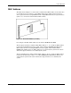
MAC Address
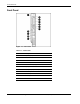
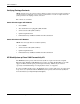
The label shown in Figure 1-5 shows where to find the Base MAC address of the switch. It is
not actually used on any interface. Actual MAC addresses that will be used for interfaces
such as physical interfaces (GigabitEthernet 0/1 to GigabitEthernet 0/24) or logical interfaces
(Vlan1, etc.) can be derived from the Base MAC address.
Figure 1-5: Base MAC Address (on label)
For example, if the Base MAC address for the switch is 00:0B:FC:FC:5B:00:
The first physical interface will be the Base MAC address + 1. As a result, the MAC address
for the first Gigabit Ethernet interface (gi0/1, when enabled) is 00:0B:FC:FC:5B:01. The
MAC address for the second Gigabit Ethernet interface (gi0/2, when enabled) will be
00:0B:FC:FC:5B:02 (and so on). MAC addresses are assigned by the system in the order in
which these physical interfaces are enabled by the system.
The first VLAN interface will be the Base MAC address + 40. As a result, the MAC address
for the first VLAN interface (Vlan1, etc.) will be 00:0B:FC:FC:5B:40. MAC addresses are
assigned by the system in the order in which these logical interfaces are enabled by the
system.
Cisco Gigabit Ethernet Switch Module for HP BladeSystem p-Class Hardware Installation Guide 1-9