
Cisco Gigabit Ethernet Switch Module for HP BladeSystem p-Class Hardware Installation Guide

Switch Installation
Table 2-1: Fiber-Optic SFP Module Port Cabling Specifications
SFP Module Wavelength
(nanometers)
Fiber Type Core Size
(micron)
Modal
Bandwidth
(MHz/km)
Cable Distance
1000BASE-SX 850 MMF 62.5
62.5
50
50
160
200
400
500
722 feet (220 m)
902 feet (275 m)
1640 feet (500 m)
1804 feet (550 m)
10/100/1000BASE-T 328 feet (100 meters)
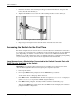
Installing a Switch
If the server blade enclosure has power applied, the switch automatically begins to power up
when installed. As the switch powers on, it begins POST, a series of tests that runs
automatically to ensure that the switch functions properly. When the switch begins POST, the
System, Status, Duplex, and Speed LEDs turn green. The System LED blinks green, and the
other LEDs remain solid green.
When the POST completes successfully, the System LED remains green. The other LEDs
turn off and then reflect the switch operating status. If the POST does not complete
successfully, then the System LED will be Amber.
After the switch powers up, refer to Appendix D, “Configuring the Switch Using CLI”, in
this guide for more information on how to configure the switch.
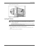
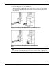
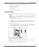
To install a new switch:
CAUTION: Pressing the Pwr/Rst button while the power status LED is green will reset the
switch.
CAUTION: Do not install or remove the switch with the SFP modules already inserted. This
may damage the SFP modules.
NOTE: If the server blade enclosure does not have power applied, refer to the System Setup and
Installation Guide for the server blade enclosure.
2-4 Cisco Gigabit Ethernet Switch Module for HP BladeSystem p-Class Hardware Installation Guide