
Cisco Gigabit Ethernet Switch Module for HP BladeSystem p-Class Hardware Installation Guide

Switch Installation
• Syslog messages are enabled and are displayed on the console.
•
•
•
•
SNMP is disabled (Version 1).
No ACLs are configured.
QoS is disabled.
No EtherChannels are configured.
Cabling the Switch
After installing the switch hardware and planning the configuration, cable the switch to your
network.
IMPORTANT: If you are replacing an existing CGESM, or upgrading from a GbE2 Interconnect Switch,
a GbE Interconnect Switch, an RJ-45 Patch Panel 2, or an RJ-45 Patch Panel, and you have strict
security requirements:
• Do not cable the switch until after configuration.
Or
• Connect the switch to the optional Diagnostic Station. The Diagnostic Station enables you to power
up, configure, and diagnose a ProLiant p-Class server blade or a switch outside of the rack
environment.
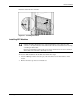
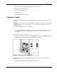
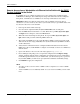
To connect the switch to the network:
1. Connect your network cables to the 10/100/1000BASE-T copper or 1000BASE-SX fiber
uplink SFP modules (labeled below as Port 19, 20, 21, and 22).
Figure 2-4: Connecting to the SFP Modules
NOTE: When connecting to 10/100/1000BASE-T SFP modules, be sure to use a twisted four-pair,
Category 5 cable.
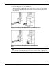
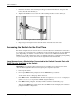
2. Gather your network cables for the right side of the rack.
Cisco Gigabit Ethernet Switch Module for HP BladeSystem p-Class Hardware Installation Guide 2-9